
Method and device for inserting needles

a needle and needle technology, applied in the field of needle insertion, can solve the problem that the pressure generated by the needle cannot therefore oppose the formation, and achieve the effect of minimizing stress and improving tissue perforation

Active Publication Date: 2014-10-02
DEBIOTECH SA
View PDF16 Cites 33 Cited by
  • Summary
  • Abstract
  • Description
  • Claims
  • Application Information

AI Technical Summary

Benefits of technology

The invention relates to a mechanism and method for maintaining a force during injection using needles, such as microneedles, into dermis. The needle can decelerate in the tissue because of its elasticity, allowing partial or total spring back to the state of equilibrium. The needle can move freely over a certain distance, but a hard or partial limitation may prevent it from returning backward. The needle will position itself at the point of equilibrium between the elastic force of the tissue and this potential opposing force. The opposing force needs not to create any pressure within the tissue that might prevent or limit correct diffusion of the substance that is to be infused.

Problems solved by technology

The pressure generated by these needles cannot therefore oppose the formation of papules which are brought about by the intradermal injection.

Method used


Image

  • Method and device for inserting needles
  • Method and device for inserting needles
  • Method and device for inserting needles

Examples


Embodiment Construction

[0021]The invention will be described in greater detail hereinbelow through some nonlimiting embodiments illustrated by figures.

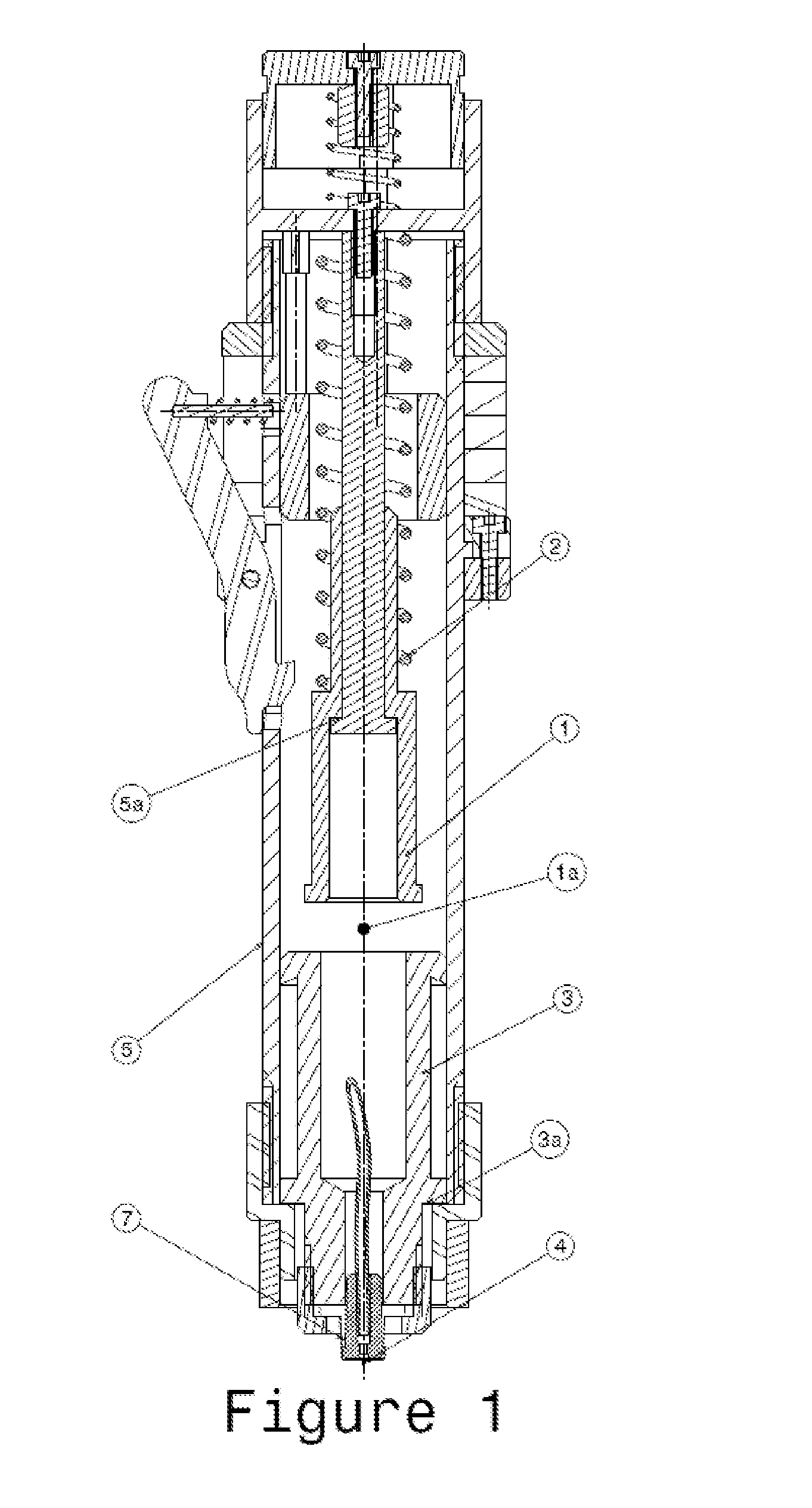
[0022]FIG. 1: Depiction of one embodiment of a device according to the invention. A needle (4) is secured to a piston (3) via a connector (7). The thruster (1) is released behind the piston (3), and the empty space (1a) for sliding can be seen between the two of them.

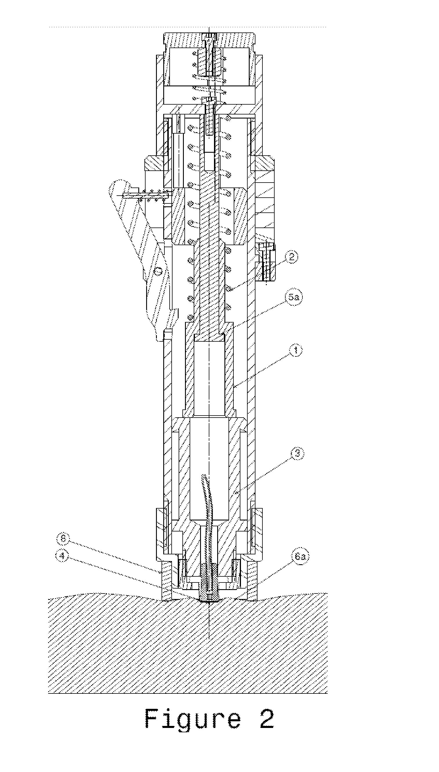
[0023]FIG. 2: In this preferred configuration, the device is placed on the tissue (6a) via contact with an outer ring (8). The device has been armed and triggered. The thruster (1) has pushed the piston (3) and has just come into abutment (5a) against a stop (cf. stem in the thruster). The piston (3) will continue its travel under the effect of inertia. For this configuration, the instant at which the piston (3) will detach from the thruster (1) corresponds on average to the instant at which the needle (4) begins to penetrate the tissue.

[0024]FIG. 3: Same device as that of FIG. 2. The piston (3...


PUM


Abstract

The invention relates to a device for inserting needles, including a body defined by a proximal end and a distal end, a mounting movably mounted inside the body, at least one needle secured to the mounting, a drive means suitable for driving the mounting towards said distal end, said mounting comprising a distal surface onto which the needle projects, said distal end comprising a contact area intended for contacting the tissue, the mounting being configured so as to reach a position, after activating the driving means, in which the distal surface thereof, relative to said proximal end, is more distant than said contact area, wherein the device is further configured so as to enable a gradual passive return movement of the mounting once said position has been reached.

Description

FIELD OF THE INVENTION[0001]The present invention relates to the insertion of needles, particularly microneedles. This may be used for intradermal or subcutaneous injection of solutions.PRIOR ART[0002]Devices for the insertion of microneedles are disclosed in the following documents: U.S. Pat. No. 6,743,211, U.S. Pat. No. 4,886,499, U.S. Pat. No. 7,083,592 and US 20100030148.GENERAL DESCRIPTION OF THE INVENTION[0003]The present invention constitutes an improvement over the methods and devices of the prior art. It is characterized in particular in that the tissue can be struck by one or more microneedles at relatively high speeds, typically of the order of 7 m / s, while at the same time allowing the tissue to deaden the impact over a certain distance, this having the effect of improving the perforation of the tissue and of returning this tissue to a stable state of equilibrium, thereby minimizing stresses.In the context of the present invention, the microneedles are free of any physic...

Claims


Application Information

Patent Timeline
Patent Type & Authority Applications(United States)
IPC IPC(8): A61M37/00
CPCA61M37/0015A61M2037/0061A61M2037/0023A61M5/158A61M5/46A61M2005/1585A61M2005/206A61M5/2033A61M2005/2026
Inventor LEMAIRE, PIERREDA ROS, JEROME
Owner DEBIOTECH SA
Learn More