Shipping method for co2 storage and import of cng

a technology of co2 storage and co2 import, which is applied in the direction of passenger handling apparatus, container discharge method, special purpose vessel, etc., can solve the problems of large distance, public opposition, safety concerns, political unwillingness, etc., and achieve the effect of reducing the cost of transporting carbon dioxid

Inactive Publication Date: 2014-10-09
STAMICARBON BV
View PDF2 Cites 16 Cited by
  • Summary
  • Abstract
  • Description
  • Claims
  • Application Information

AI Technical Summary

Benefits of technology

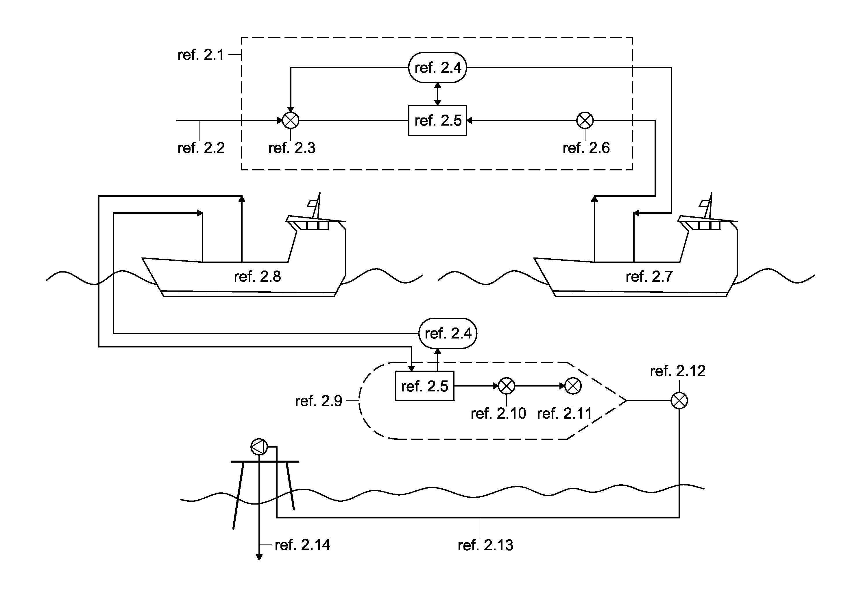
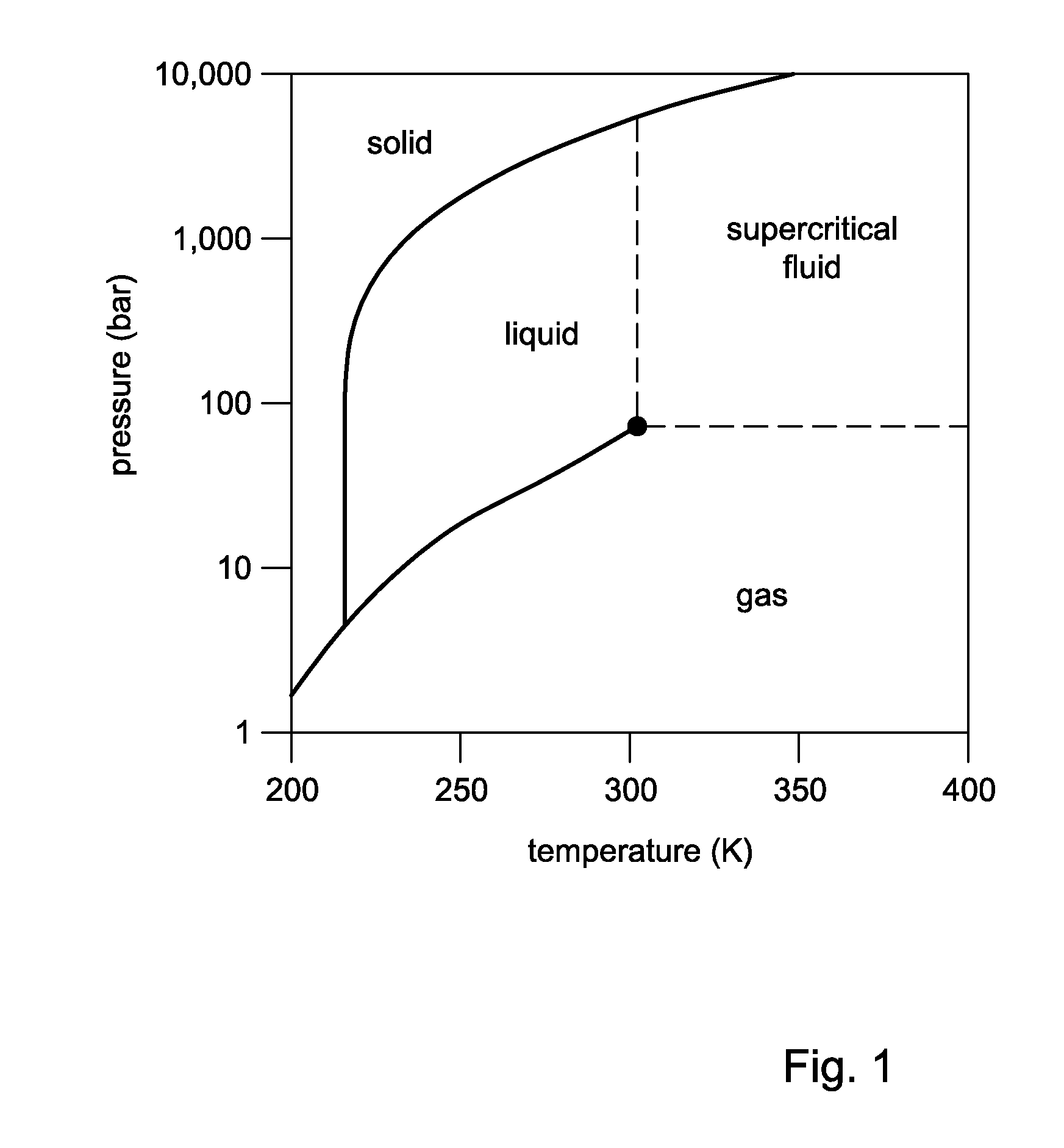
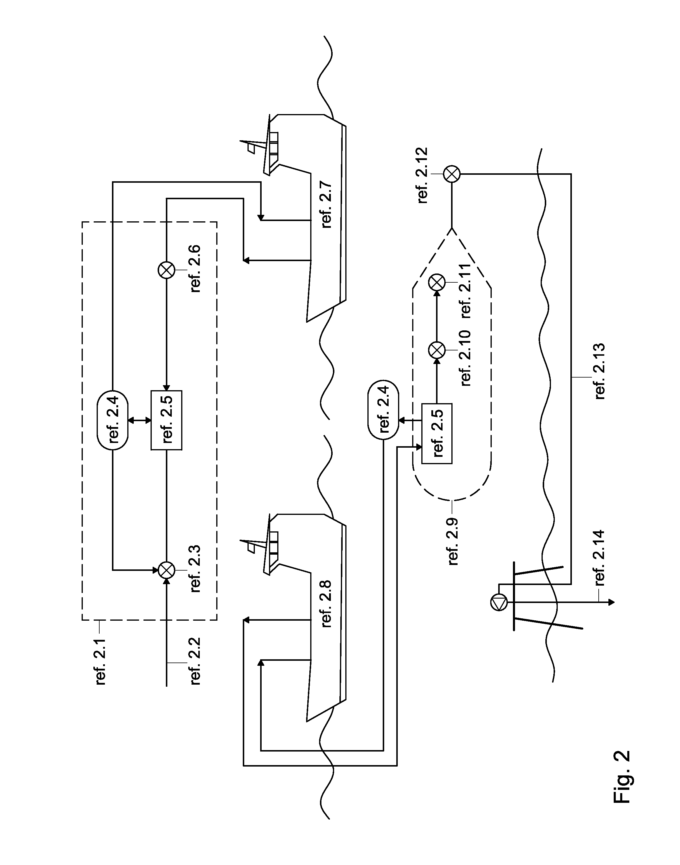
[0009]In order to better address one or more of the foregoing desires, the invention, in one aspect, provides a method for transporting captured carbon dioxide (CO2) to an off-shore location, wherein the CO2 is transported by ship, with the CO2 being at a temperature between −25° C. and +25° C., and under a pressure that is sufficiently high for the CO2 to be in a liquid state, wherein the transport of CO2 is combined with transport of compressed natural gas (CNG), such that one way a ship transports CO2 and the reverse way the ship transports the CNG, wherein one or more ships are used having tubular containment equipment for the storage of CO2, and wherein the CO2 and the CNG have substantially the same pressure.

Problems solved by technology

Despite the desire to reduce greenhouse gas emission, which is well acknowledged in society at large, the sequestration of CO2 in underground structures in or nearby inhabited areas frequently results in safety concerns, public opposition, and political unwillingness.
Whilst this serves to avoid the environmental and permit problems of reinjection in on-shore structures, it comes with practical and economical disadvantages of the need to transport the carbon dioxide over large distances, by sea.
Such transport can be done by pipeline, but the distance to the location, or the technical difficulties to lay a pipe line will mean that transport had better be done by ship.

Method used


Image

  • Shipping method for co2 storage and import of cng
  • Shipping method for co2 storage and import of cng
  • Shipping method for co2 storage and import of cng

Examples


example

[0062]High pressure shipping (170 bar), as illustrated in FIG. 7.

[0063]A ship is used comprising a tubular containment system based on 28″ inches pipes with 20.6 mm thickness. The size of the ship is such as to be able to contain a total of 2.304 strings of 28″ 48 m length (split in 32 modules of 24 strings in each of the three ship's compartments).

[0064]The ship's size will be as follows:

Length250 m Beam44 mDepth34 m

[0065]Alternatively, the ship is provided with a “coselle” type of containment, using coselles made with 6″ pipe, as considered by “sea NG” company, leading to a larger ship size.

[0066]The total weight of the containment is 47,000 t, offering a volume of 40.500 m3 as internal volume.

[0067]The ship's containment system is operated at −8° C. in order to optimize the volume of stranded gas capacity which is favored by the higher gas compressibility factor at such a temperature.

[0068]The ship's 40.500 m3 internal volume provides a storage capacity of 42.708 t of CO2. This a...


PUM


Abstract

Disclosed is a method of transporting CO2 by ship for the purpose of storage in the ocean. The CO2 is transported at a temperature between −25° C. and +25° C., and under a pressure that is sufficiently high for the CO2 to be in a liquid or supercritical state. The choice of temperature/pressure conditions for the CO2 enables the transport of CO2 one way to be effectively combined with transport of compressed natural gas (CNG) the other way. Ships can be used that have relatively cheap tubular containment equipment similar to the type normally used for CNG but with lower pressure and not subject to cyclic thermal and mechanical effects of pressurizing and depressurizing.

Description

FIELD OF THE INVENTION[0001]The invention pertains to a method of transport and off-shore underground storage of carbon dioxide (CO2). The invention particularly pertains to a method of shipping and storage of CO2 in conjunction with shipping of compressed natural gas on the return trip.BACKGROUND OF THE INVENTION[0002]Carbon dioxide (CO2) is an inevitable product of the burning of fossil fuels. These gas emissions, frequently referred to as “greenhouse gases,” are acknowledged to contribute substantially to global warming. Hence, it is desired to prevent, or at least reduce, CO2 emission.[0003]One method to achieve this is sequestration of CO2 Herein the CO2 is captured and stored in a location where it can be considered to be closed-off in a safe way, such as in underground structures.[0004]Despite the desire to reduce greenhouse gas emission, which is well acknowledged in society at large, the sequestration of CO2 in underground structures in or nearby inhabited areas frequently ...

Claims


Application Information

Patent Timeline
Patent Type & Authority Applications(United States)
IPC IPC(8): B63B25/14F17C1/00B63B27/24
CPCB63B25/14F17C1/002B63B27/24F17C5/06F17C7/00F17C7/02F17C13/082F17C2221/013F17C2221/033F17C2223/0115F17C2223/0123F17C2223/0153F17C2223/033F17C2223/035F17C2260/02F17C2260/04F17C2265/06F17C2270/0105F17C2270/0155
Inventor TROLLUX, JACQUES FRANCOIS ANDRE
Owner STAMICARBON BV
Why Eureka
Try Eureka