
Electronic cigarette

a technology of electronic cigarettes and heated products, which is applied in the direction of inhalators, tobacco, food science, etc., can solve the problems of reducing the service life of electronic cigarettes, affecting the taste of electronic cigarettes, and reducing the length of electronic cigarettes. , to achieve the effect of convenient carrying and reduced whole length of electronic cigarettes

Inactive Publication Date: 2014-10-09
HUIZHOU KIMREE TECH
View PDF4 Cites 91 Cited by
  • Summary
  • Abstract
  • Description
  • Claims
  • Application Information

AI Technical Summary

Benefits of technology

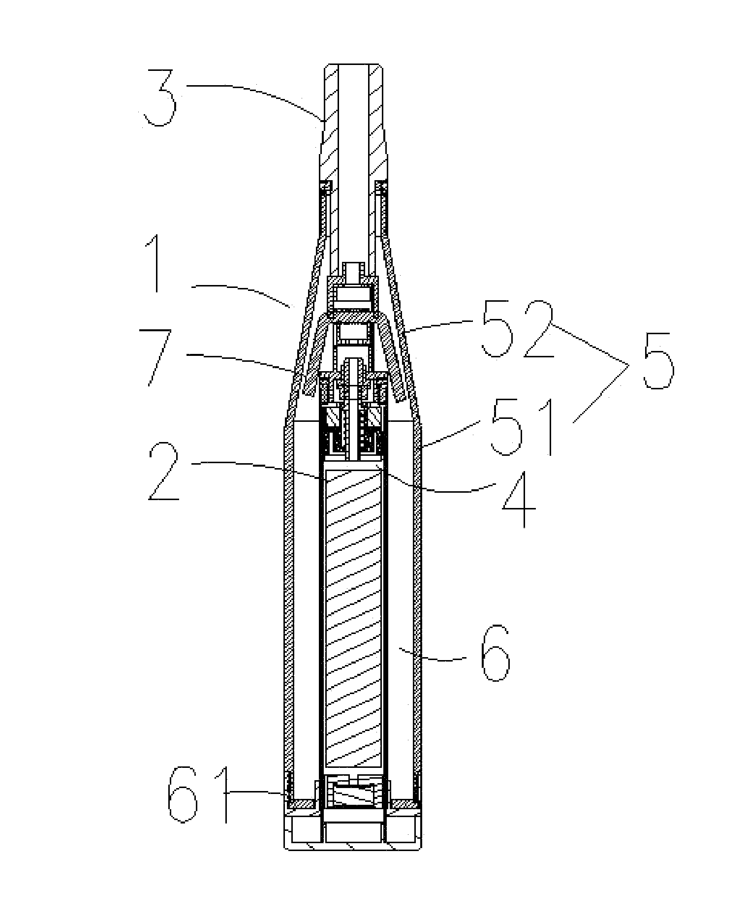
The present invention provides an electronic cigarette with detachable parts, making it easier to replace the atomizing core. Additionally, the battery pipe can be inserted into the atomizer, reducing the overall length of the electronic cigarette and making it easier to carry.

Problems solved by technology

An electronic cigarette comprises an atomizer and a battery pipe, in the prior art, the atomizer and the battery pipe are both serially connected, and thus the body of the cigarette is too long to be carried.
Further, the atomizing core component inside the atomizer is not replaceable, the atomizing core component may easily get damaged and dirties after long term use for many times, and the taste of the electronic cigarette is getting bad.

Method used


Image

  • Electronic cigarette
  • Electronic cigarette
  • Electronic cigarette

Examples


first embodiment

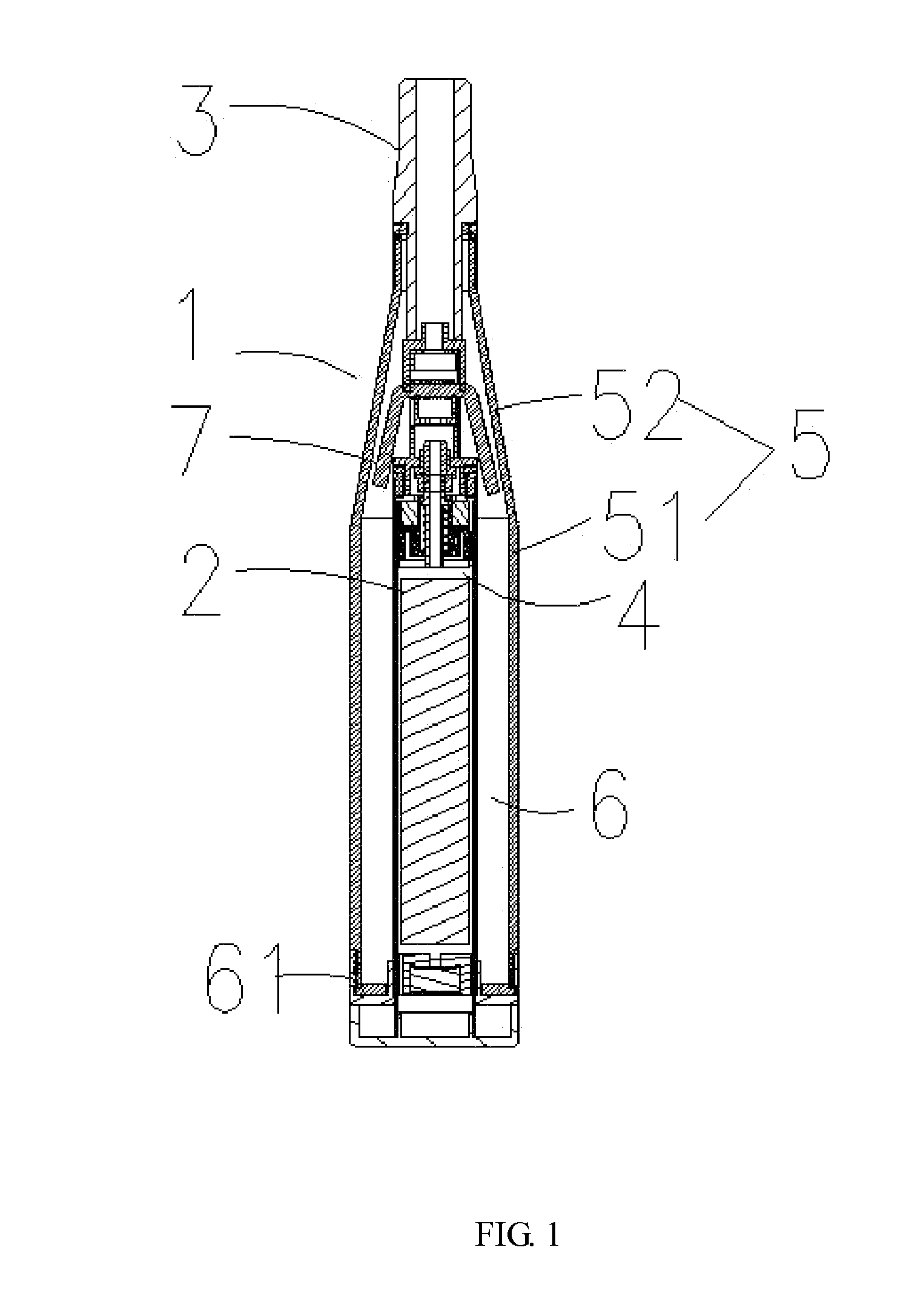
[0048]The battery pipe 2 can be connected with the atomizer 1 through magnetic connection or threaded connection. Below is a first embodiment that the battery pipe 2 is magnetically connected with the atomizer 1.

[0049]As shown in FIG. 1 and FIG. 4, in this instance, a magnet 21 is fixed on the upper end of the battery pipe 2, and via the attraction between the magnet 21 and the battery chamber 4, the battery pipe 2 is connected to the atomizer 1. Specifically, this connection is obtained by the attraction between the magnet 21 and the connecting position of the first connector 74 and the battery chamber 4. A lower electrode 82 runs through the middle of the magnet 21, and the upper electrode 81 is attached to the lower electrode 82.

[0050]Specifically, one way of fixing the magnet 21 to the upper end of the battery pipe 2 is that, by mounting a first fixing sleeve 201 on the top of the magnet 21, in the fixing sleeve, configuring a first insulated covering 202 interference fitting wi...

second embodiment

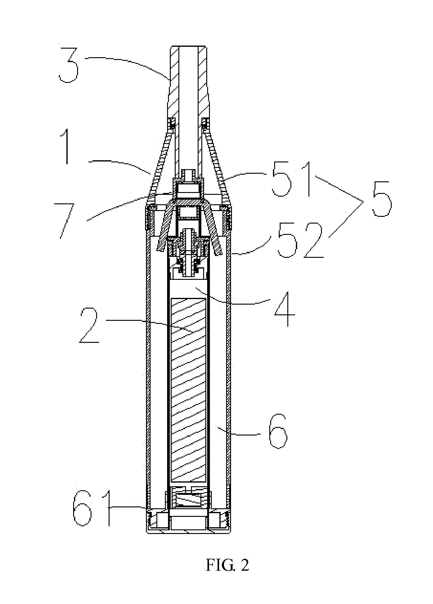
[0054]Below is a second embodiment that the battery pipe 2 is connected with the atomizer by way of threaded connection, and particularly by the threaded connection between the tar storing chamber 6 and the battery pipe 2.

[0055]As shown in FIG. 2 and FIG. 5, in this instance, there is no magnet 21 on top of the battery pip2, and instead a second fixing sleeve 207 is mounted on the upper end of the battery pipe 2, and the lower electrode 82 is inserted into the second fixing sleeve 207.

[0056]The way to connect the lower electrode 82 to the top of the battery pipe 2 is that, by connecting the top of the battery pipe 2 to the second fixing sleeve 207 via interference fitting, inserting the lower electrode 82 into the second fixing sleeve 207, and configuring a insulated ring between the second fixing sleeve 207 and the lower electrode 82, the insulated ring is mounted to the outer side of the lower electrode 82 and gets compressed, thus fixing the lower electrode 82 in the second sleev...


PUM


Abstract

This invention relates to an electronic cigarette, comprising an atomizer and a battery pipe; an end of the atomizer is connected to a sucking mouth component, a battery chamber is mounted in the atomizer, and the battery pipe is fixedly inserted in the battery chamber; the atomizer also includes an atomizing core component detachably configured between the battery pipe and the sucking mouth component. By implementing the electronic cigarette of the invention, it is convenient in carrying, and the atomizing core component is replaceable, and convenient to use.

Description

CROSS-REFERENCE TO RELATED APPLICATIONS[0001]This non-provisional application claims priorities under 35 U.S.C. § 119(a) on Patent Application No. 201320165796.7 filed in P.R. China on Apr. 3, 2013, the entire contents of which are hereby incorporated by reference.FIELD OF THE INVENTION[0002]This invention relates to the field of electronic heated product, and more particularly to an electronic cigarette.BACKGROUND OF THE INVENTION[0003]An electronic cigarette comprises an atomizer and a battery pipe, in the prior art, the atomizer and the battery pipe are both serially connected, and thus the body of the cigarette is too long to be carried. Further, the atomizing core component inside the atomizer is not replaceable, the atomizing core component may easily get damaged and dirties after long term use for many times, and the taste of the electronic cigarette is getting bad.SUMMARY OF THE INVENTION[0004]The technical problem to solve in the invention is to deal with the defects in the...

Claims


Application Information

Patent Timeline
IPC IPC(8): A24F47/00A24F40/10A24F40/40
CPCA24F47/008A24F40/10A24F40/40A61M15/06
Inventor LIU, QIUMING
Owner HUIZHOU KIMREE TECH
Learn More