Pedestal for tracking antenna

a technology for pedestals and antennas, applied in the direction of antennas, machine supports, domestic objects, etc., can solve the problems of antennas mounted on ships antennas that are subject to other environmental stresses, and may need additional stabilization

Active Publication Date: 2014-10-09
SPACECOM HLDG
View PDF16 Cites 22 Cited by
  • Summary
  • Abstract
  • Description
  • Claims
  • Application Information

AI Technical Summary

Benefits of technology

[0015]a fifth frame supporting the tracking antenna and being rotatably mounted on the elevation axis support of the fourth frame to rotate about the third axis. It is preferred that the first frame holds at least part of a first horizontal linear bearing assembly, and that a lower frame part of the second frame is slidably interconnected to the first frame via the first horizontal linear bearing assembly, said first linear bearing assembly including dampers or suspension members for dampening linear slide movement of the second frame along the first linear bearing assembly and thereby for dampening the relative movement of the second frame to the first frame.
[0019]a second frame with a lower frame part slidably interconnected to the first frame via the first horizontal linear bearing assembly, said first linear bearing assembly including dampers or suspension members for dampening linear slide movement of the second frame along the first linear bearing assembly and thereby for dampening the relative movement of the second frame to the first frame;
[0029]The present invention also covers one or more embodiments, wherein the pedestal further comprises a vibration isolation assembly interconnecting the second frame and the third frame. Here, the vibration isolation assembly may comprise a dampening and / or suspension member with the second and third frames being connected via said dampening or suspension member. The dampening or suspension member interconnecting the second and third frames may be of a wire rope type, which thereby may isolate the third frame from vibration / shock of the base and first frame.
[0037]By use of a pedestal according to one or more embodiments of the present invention, stabilizing the pointing of a mobile tracking antenna can be obtained with simple stepper motors driving frame rotation about the three pedestal axes, wherein relatively simple servo systems can be used to control the stepper motors in a closed loop arrangement without causing cycle slip of the stepper motors. Direct control of angular position of the antenna may be enabled by use of a transfer function of lowest or a relatively low order in the servo systems.
[0038]By using a pedestal according to the principles of the present invention, friction of bearings and transmission elements should not affect the accuracy of the servo systems for stabilizing the pointing of the antenna. Also imperfect balance of the masses rotating about the azimuth, elevation and cross-elevation axis should not affect the accuracy of the servo systems. Furthermore, the degree of damping of the sliding and rotational movements of the frame structures relative to each other should easily be controlled by friction in linear bearings and dampening in the rope type damper.

Problems solved by technology

When a ship changes its geographical position, or when the satellite changes its position in orbit, and when the ship rolls, pitches, yaws and turns, an antenna mounted on the ship will tend to become misdirected.
In addition to these disturbances the antenna will be subjected to other environmental stresses such as shocks caused by wave pounding.
While this pedestal is quite effective, additional stabilization may be necessary, for example, during extremely rough seas and gale force winds.
However, the servo systems required to control the angular position of the antenna mounted on this pedestal is rather complex and sensitive to imperfect balance, bearing friction and imposed vibration and shock.

Method used


Image

  • Pedestal for tracking antenna
  • Pedestal for tracking antenna
  • Pedestal for tracking antenna

Examples


Embodiment Construction

[0051]In Table 1 is given a list of designations and reference numerals used in FIGS. 1-10.

[0052]Table 1. List of Designations

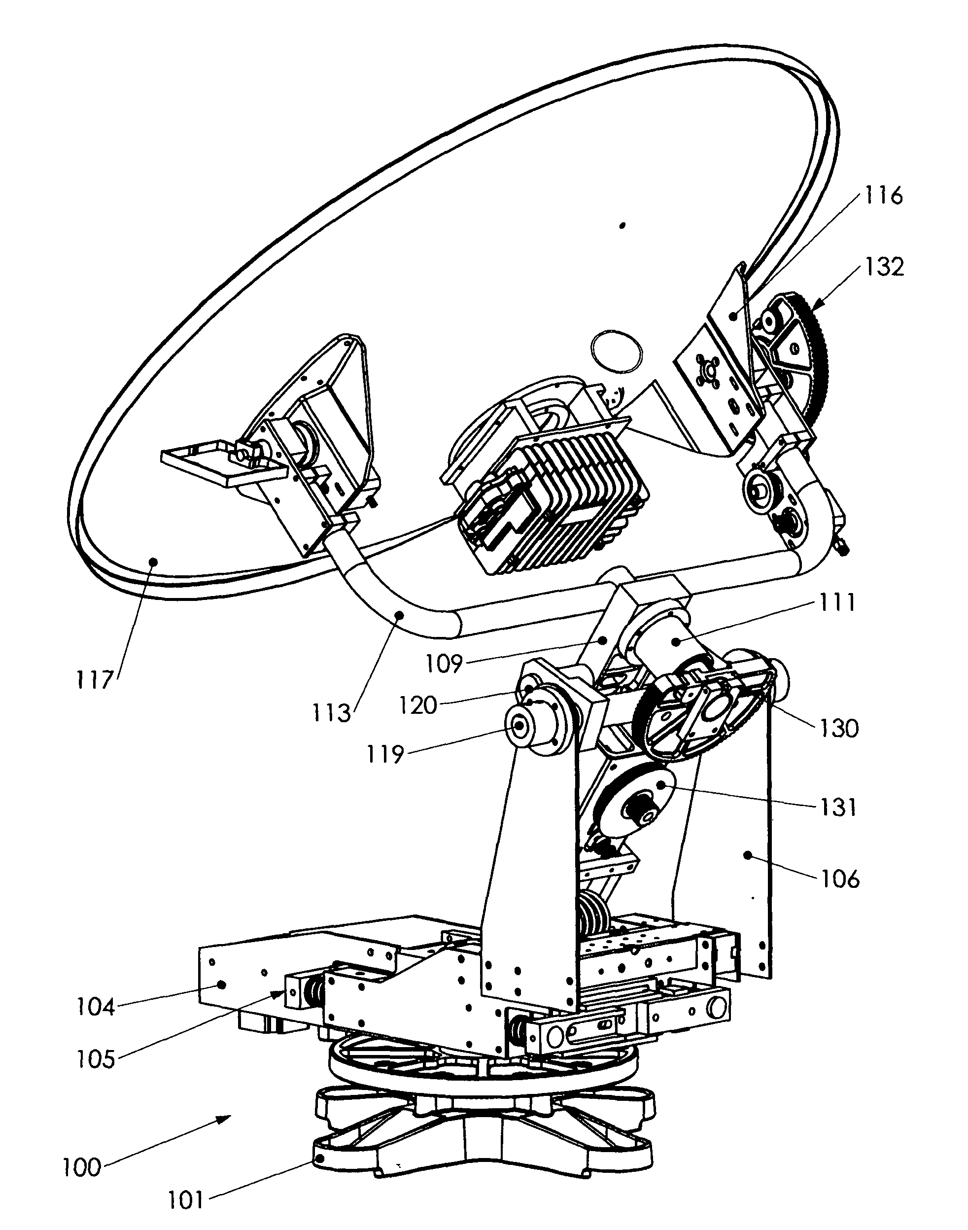
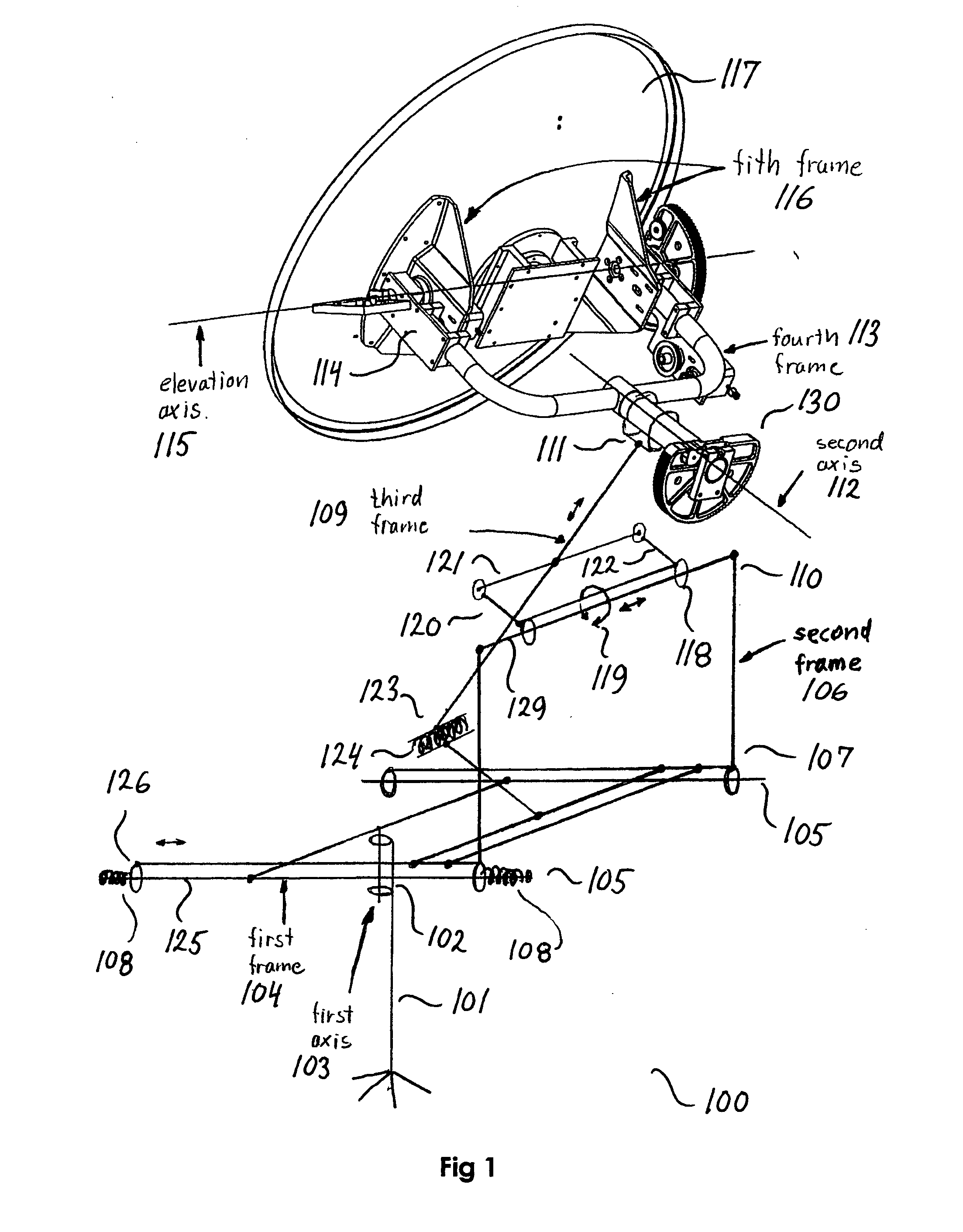
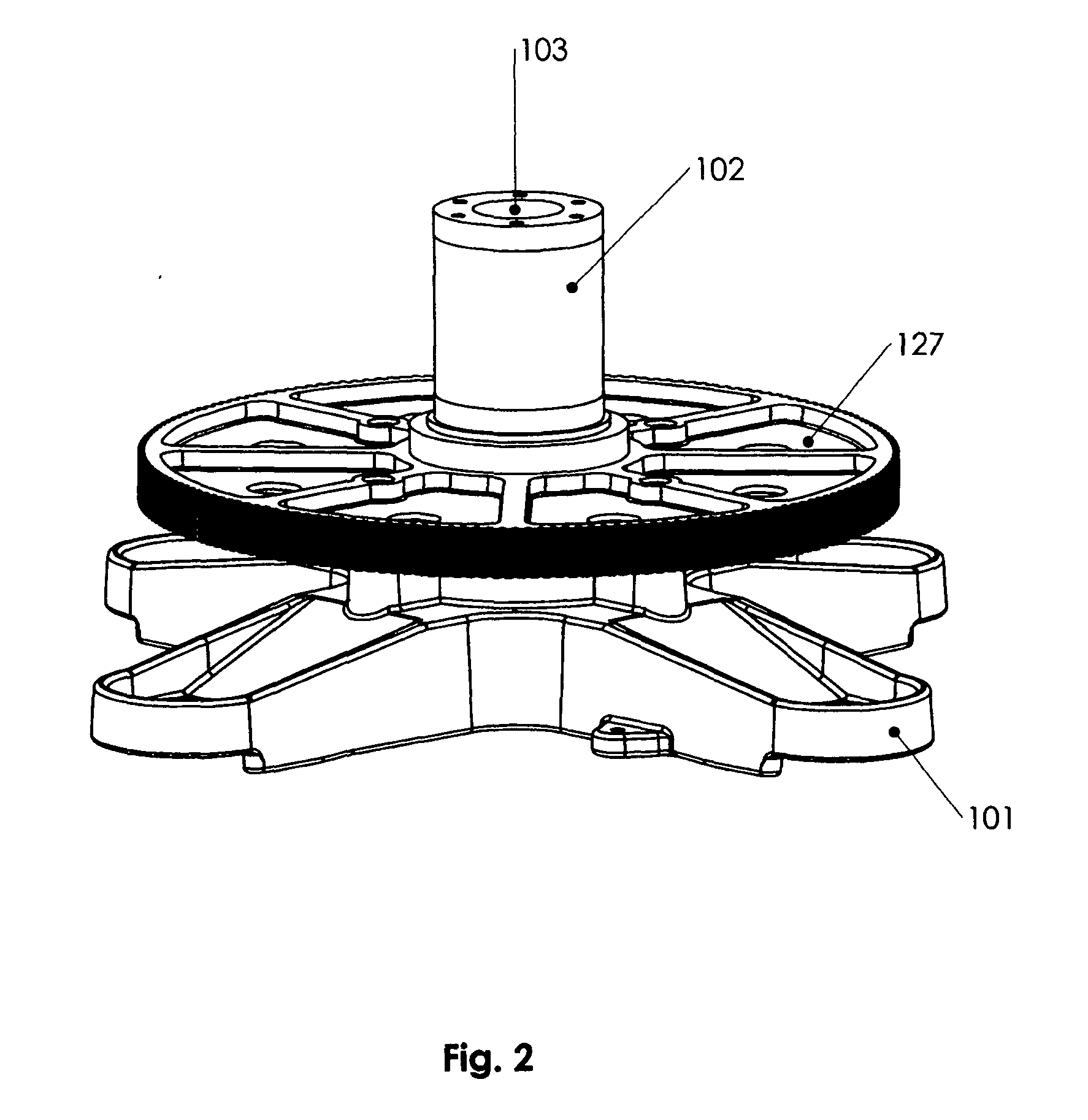
[0053]100: “three-axes pedestal”;

[0054]101: “base support”;

[0055]102: “azimuth axis support of base support”;

[0056]103: “first axis or azimuth axis”;

[0057]104: “first frame”;

[0058]105: “first horizontal linear bearing assembly”;

[0059]106: “second frame”;

[0060]107: “lower frame part of second frame”;

[0061]108: “dampers or suspension members of first linear bearing assembly;

[0062]109: “third frame”;

[0063]110: “upper part of second frame”;

[0064]111: “cross-elevation axis support of third frame”;

[0065]112: “second axis or cross-elevation axis”;

[0066]113: “fourth frame”;

[0067]114: “elevation axis support of fourth frame”;

[0068]115: “third axis or elevation axis”;

[0069]116: “fifth frame”;

[0070]117: “tracking antenna”;

[0071]118: “second linear bearing assembly”;

[0072]119: “rotation axis provided by the second linear bearing assembly for rotation of the third frame a...


PUM


Abstract

There is provided a three-axes pedestal for stabilizing the pointing of a mobile tracking antenna. The pedestal comprises a base support with an azimuth axis support having a centerline defining a first axis or azimuth axis, and a first frame being rotatably mounted on the azimuth axis support to rotate about the first axis, where the first frame may hold at least part of a first horizontal linear bearing assembly. The pedestal further comprises a second frame with a lower frame part, which may be slidably interconnected to the first frame via the first horizontal linear bearing assembly. The first linear bearing assembly may include dampers or suspension members for dampening linear slide movement of the second frame along the first linear bearing assembly and thereby for dampening the relative movement of the second frame to the first frame. The pedestal also comprises a third frame interconnected to an upper part of the second frame, where the third frame holds a cross-elevation axis support with a centerline defining a second axis or cross-elevation axis. Furthermore, the pedestal comprises a fourth frame being rotatably mounted on the cross-elevation axis support of the third frame to rotate about the second axis, where the fourth frame holds an elevation axis support with a centerline defining a third axis or elevation axis. The pedestal also comprises a fifth frame supporting the tracking antenna, which fifth frame is rotatably mounted on the elevation axis support of the fourth frame to rotate about the third axis. The upper part of the second frame may hold a second linear bearing assembly, with the third frame being interconnected to the second frame via the second linear bearing assembly, and with the second linear bearing assembly providing a direction of linear slide movement and an axis of rotation for the third frame, thereby providing an axis of rotation for the second axis in a plane perpendicular to the direction of linear slide movement provided by the second linear bearing assembly.

Description

FIELD OF THE INVENTION[0001]The present invention relates to antenna pedestals and particularly to satellite tracking antenna pedestals used on ships and other mobile applications.BACKGROUND OF THE INVENTION[0002]The invention is especially suitable for use aboard ship wherein an antenna is operated to track a transmitting station, such as a communications satellite, notwithstanding roll, pitch, yaw, and turn motions of a ship at sea.[0003]Antennas used in shipboard satellite communication terminals typically are highly directive. For such antennas to operate effectively they must be pointed continuously and accurately in the direction toward the satellite.[0004]When a ship changes its geographical position, or when the satellite changes its position in orbit, and when the ship rolls, pitches, yaws and turns, an antenna mounted on the ship will tend to become misdirected. In addition to these disturbances the antenna will be subjected to other environmental stresses such as shocks c...

Claims


Application Information

Patent Timeline
Patent Type & Authority Applications(United States)
IPC IPC(8): H01Q1/18H01Q3/08
CPCH01Q1/005H01Q3/08H01Q1/34H01Q1/18H01Q1/12
Inventor NIELSEN, PETER TROELS
Owner SPACECOM HLDG
Why Eureka
Try Eureka