
LED lighting device and an ledlighting network system

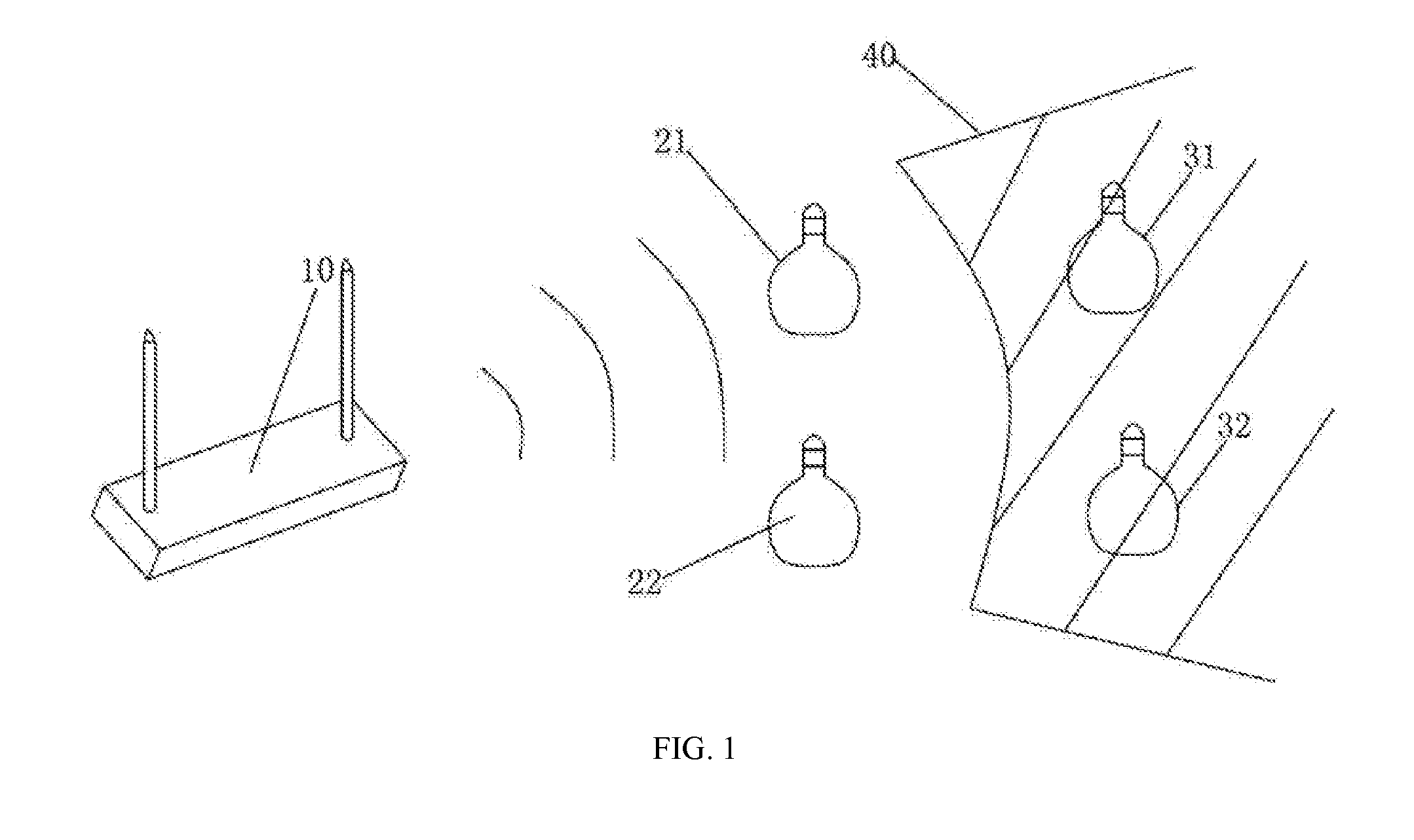
a lighting device and led lighting technology, applied in lighting and heating equipment, process and machine control, instruments, etc., can solve the problems of limited wireless signal coverage area of traditional wireless lighting networks, less reliable and convenient use of wireless network based lighting control, and lighting devices b>31/b> and b>32/b> cannot receive wi-fi signals, etc., to achieve the effect of expanding the network coverage area

Inactive Publication Date: 2014-10-09
ZHEJIANG SHENGHUI LIGHTING
View PDF5 Cites 66 Cited by
  • Summary
  • Abstract
  • Description
  • Claims
  • Application Information

AI Technical Summary

Benefits of technology

This patent describes LED lighting devices that can connect to a network and be remotely controlled. The devices can create a network that expands beyond the range of Wi-Fi signals, making it easier to control and monitor the devices from far away. Overall, this technology allows for more flexible and efficient control of LED lighting.

Problems solved by technology

However, traditional wireless lighting networks often have limited wireless signal coverage areas because of constraints such as obstacles in the coverage area and limited signal transmission distance.
Such constraints have made the wireless network based lighting control less reliable and less convenient to use.
As s a result, lighting devices 31 and 32 cannot receive Wi-Fi signals and cannot be controlled through the Wi-Fi network.
The lighting devices also cannot transmit data among themselves.
As a result, the Wi-Fi based lighting system may be limited by the transmission distance of the Wi-Fi signals.

Method used


Image

  • LED lighting device and an ledlighting network system
  • LED lighting device and an ledlighting network system
  • LED lighting device and an ledlighting network system

Examples


Embodiment Construction

[0023]Reference will now be made in detail to exemplary embodiments of the invention, which are illustrated in the accompanying drawings. Hereinafter, embodiments consistent with the disclosure will be described with reference to drawings. Wherever possible, the same reference numbers will be used throughout the drawings to refer to the same or like parts. It is apparent that the described embodiments are some but not all of the embodiments of the present invention. Based on the disclosed embodiment, persons of ordinary skill in the art may derive other embodiments consistent with the present disclosure, all of which are within the scope of the present invention.

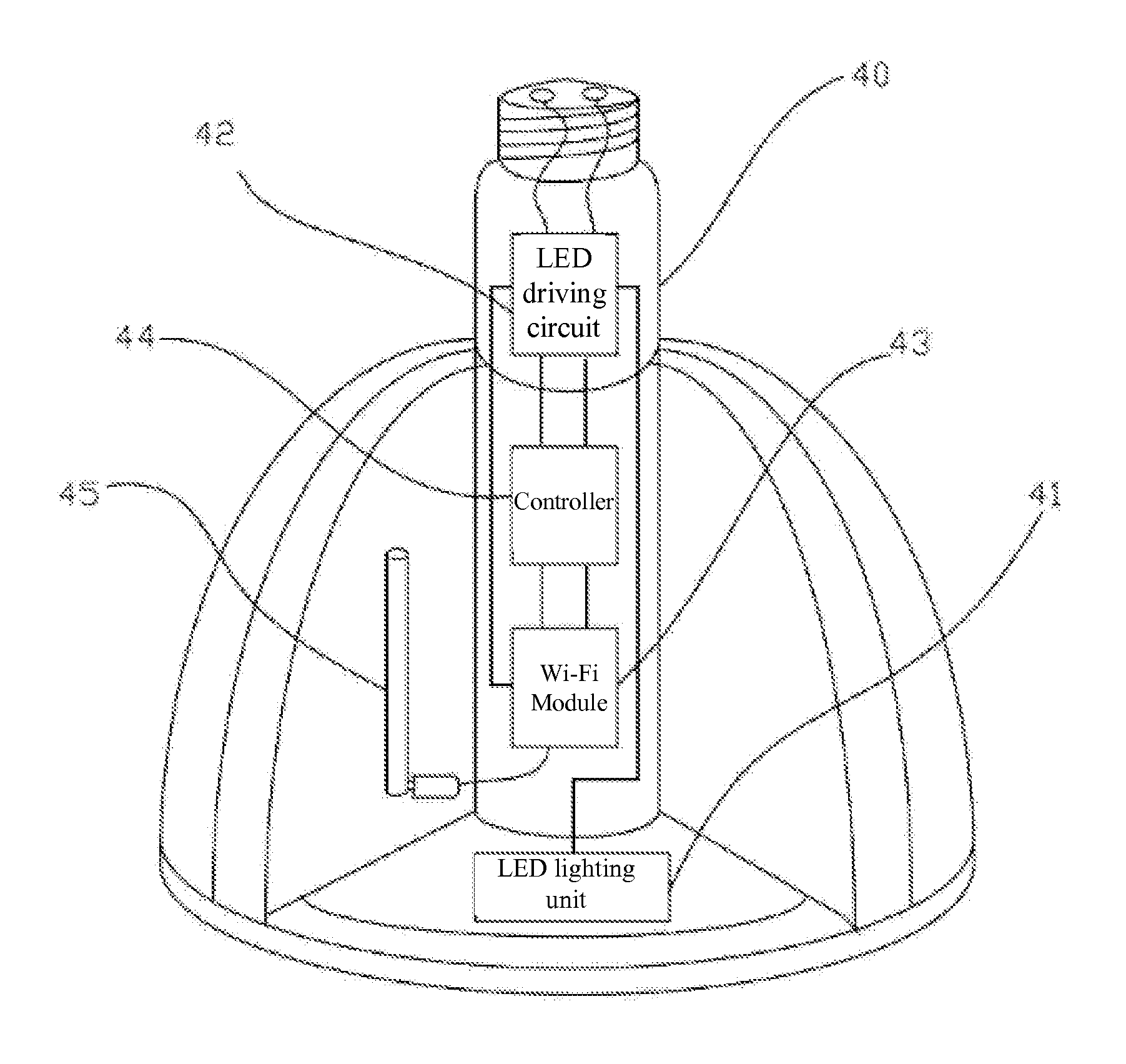
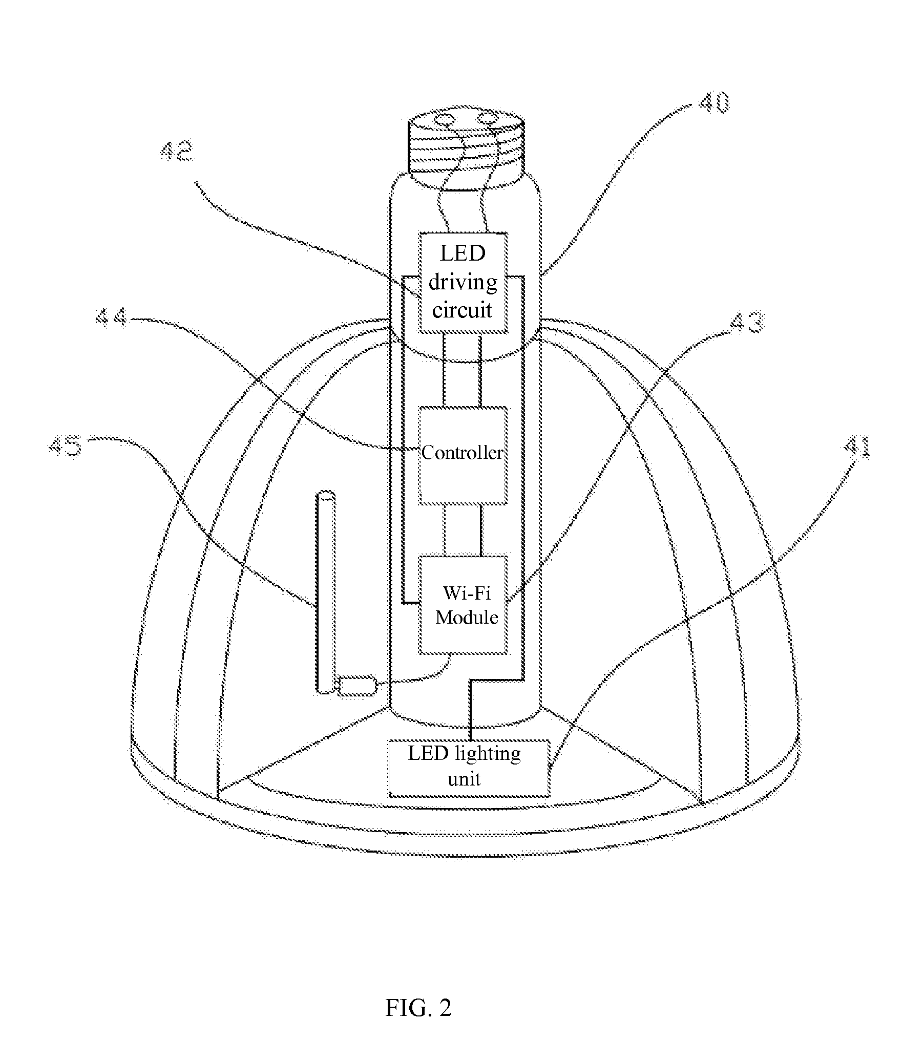
[0024]An exemplary embodiment consistent with the present disclosure is described below. FIG. 2 illustrates an exemplary LED lighting device consistent with the present disclosure. The LED lighting device includes an LED lighting unit 41, an LED driving circuit 42, a Wi-Fi module 43, and a controller 44. As shown in FIG. 2, ...


PUM


Abstract

The present invention provides an LED lighting device and an LED lighting network system. The LED lighting device includes an LED lighting unit, an LED driving circuit, a controller, and a Wi-Fi module configured to send and receive Wi-Fi signals. The LED driving circuit connects to the LED lighting unit. The controller connects to the Wi-Fi module and the driving circuit. The LED lighting network system includes two or more of the above LED lighting devices. Each LED lighting device works as a network node, which transmits received Wi-Fi data to other LED lighting devices within its coverage range. The LED lighting devices may form a mesh network. Each LED lighting device may act as a gateway, a network accessing point, or a repeater. The LED lighting network can receive and transmit Wi-Fi signals. In a mesh network, Wi-Fi signals can be transmitted from one layer of LED lighting devices to the next layer. Embodiments consistent with the present disclosure can overcome lighting network problems caused by obstacles in the Wi-Fi transmission range or the limitation of the Wi-Fi signal transmission range.

Description

CROSS-REFERENCES TO RELATED APPLICATIONS[0001]This application is a continuation in part and claims the priority of Chinese Patent Application No. 201210544078.0 (PCT / CN2012 / 086655) filed on Dec. 14, 2012, which claims the priority of Chinese Patent Application No. 201210292575.6, filed on Aug. 16, 2012. The entire contents of both Chinese Patent Applications are incorporated herein by reference.FIELD OF THE DISCLOSURE[0002]The present disclosure relates to the field of light emitting diode (LED) technologies and, more particularly, relates to LED lighting devices with Wi-Fi capacities and the related lighting network.BACKGROUND[0003]Intelligent lighting control devices and systems are well-researched topics of the new generation of lighting solutions. Currently, widely used lighting control methods include:[0004]1. Sensor Based Methods. Sensors are used to monitor operating conditions. For example, light intensity sensors may monitor the ambient brightness. Then the lighting device...

Claims


Application Information

Patent Timeline
Patent Type & Authority Applications(United States)
IPC IPC(8): H05B33/08H05B44/00
CPCH05B33/0842F21S2/00H04W84/12F21V23/0435H04W84/18F21K9/23F21Y2115/10H05B47/19H05B45/325
Inventor RUAN, JIAYANGSHEN, JINXIANG
Owner ZHEJIANG SHENGHUI LIGHTING
Features
  • Generate Ideas
  • Intellectual Property
  • Life Sciences
  • Materials
  • Tech Scout
  • Unparalleled Data Quality
  • Higher Quality Content
  • 60% Fewer Hallucinations
Learn More