Pneumatischer Antrieb und Verfahren zur Erfassung der Leistung eines pneumatischen Antriebs

a technology of pneumatic antrieb and pneumatic cylinder, which is applied in the direction of mechanical equipment, engine components, machines/engines, etc., can solve the problem of comparatively expensive components of air consumption gauges, and achieve the effect of inexpensively determined

Active Publication Date: 2014-10-16
BURKERT WERKE
View PDF2 Cites 0 Cited by
  • Summary
  • Abstract
  • Description
  • Claims
  • Application Information

AI Technical Summary

Benefits of technology

[0003]It is an object of the invention to specify a pneumatic drive, the power of which can be inexpensively determined. In addition, it is an object of the invention to specify an inexpensive method for determining the power of a pneumatic drive.
[0006]In case the pneumatic drive is already provided with an evaluation unit for other reasons, it is additionally inexpensively possible to configure this already present evaluation unit for the additionally provided energy consumption measurement. Thus, this additional function can for example be given to the evaluation unit by implementing a suitable new software. It can resort to the values metrologically accessible in the system and determine the power and the energy consumption, respectively, of the pneumatic drive based on them. The use of an expensive air consumption gauge or mass flow meter can be advantageously omitted. With a pneumatic drive according to aspects of the invention, it is instead only required to integrate an inexpensive pressure sensor and to correspondingly program the evaluation unit. Compared to conventional systems, this presents a significant economical advantage. The current power and the energy consumption of the pneumatic drive can be simply and inexpensively determined.
[0012]Corresponding to further embodiments, the measured values can be acquired over a longer period of time. Thus, the energy consumption of the pneumatic drive can also be considered over a longer period of time. The current values for the energy consumption can greatly fluctuate on short time scales due to the specific operation of the pneumatic drive. A time-averaged value of the energy consumption can be the value more meaningful for the user in some cases.
[0024]For improving the efficiency of a single-acting pneumatic drive, a fill body can be disposed in the working space. This fill body reduces the dead volume of the drive. Thus, the energy consumption of the drive can be optimized. The user obtains a corresponding indication that a potential of optimization is present based on the determined efficiencies. In times of increasing energy cost, this presents valuable information for him.
[0031]For improving the efficiency of a single-acting drive, in addition, a fill body can be disposed in the working space.

Problems solved by technology

However, air consumption gauges are comparatively expensive components such that it is desirable to find a more inexpensive way to determine the energy consumed by a pneumatic component.

Method used


Image

  • Pneumatischer Antrieb und Verfahren zur Erfassung der Leistung eines pneumatischen Antriebs
  • Pneumatischer Antrieb und Verfahren zur Erfassung der Leistung eines pneumatischen Antriebs
  • Pneumatischer Antrieb und Verfahren zur Erfassung der Leistung eines pneumatischen Antriebs

Examples


Embodiment Construction

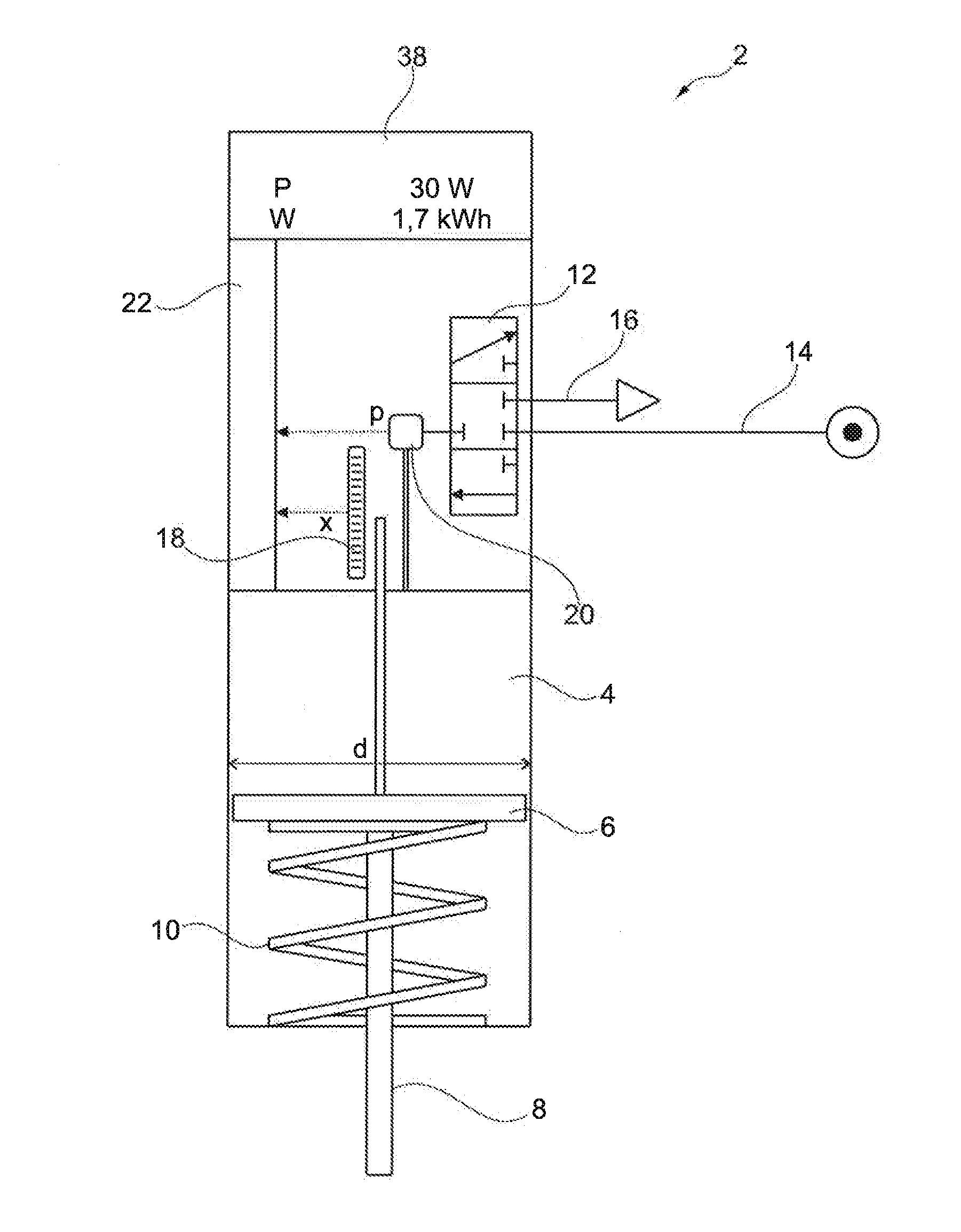
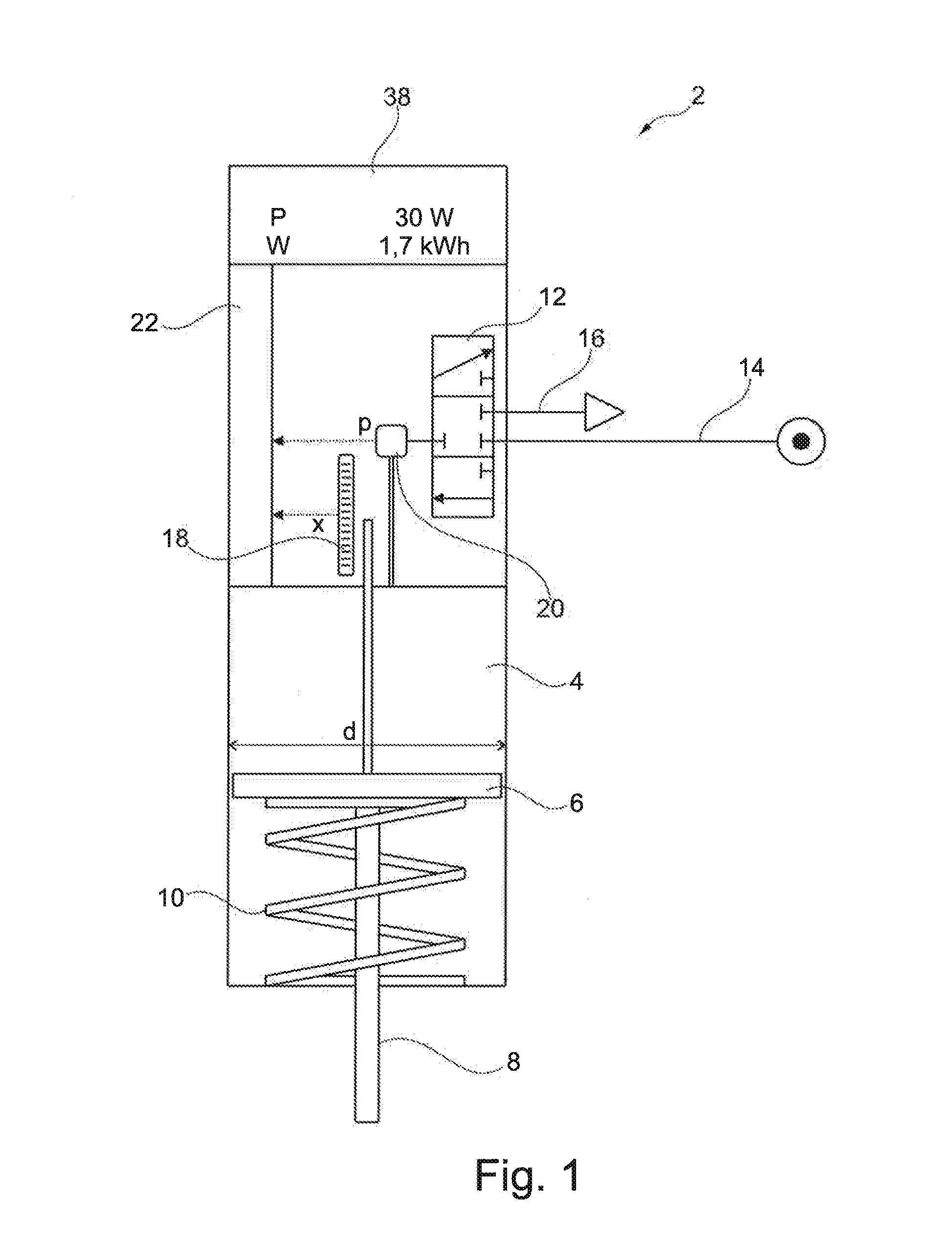
[0037]FIG. 1 is a simplified, schematic illustration of a pneumatic drive 2 according to an embodiment. It includes a working space 4, in which a piston 6 is movably disposed. The piston 6 is connected to a piston rod 8, on which the power or work provided by the pneumatic drive 2 can be transferred to a further unit. For example, a valve or a slider of a fluidic system can be actuated with the pneumatic drive 2. A further possibility is the use of the pneumatic drive 2 as a linear drive.

[0038]The embodiment of FIG. 1 shows a single-acting pneumatic drive 2. The piston 6 cooperates with a return spring 10, which keeps it in its starting position or returns it into its starting position. In order to provide a force for actuating a component connected to the pneumatic drive 2 on the piston rod 8, the working space 4 is pressurized. For this purpose, the pneumatic drive 2 includes a 3 / 3-way valve 12. Alternatively to a 3 / 3-way valve, two 3 / 2-way valves or generally an adjusting system ...


PUM


Abstract

A pneumatic drive and a method for acquiring the power of a pneumatic drive are specified. A piston is movably disposed in a working space and coupled to a path transducer. A pressure sensor is provided for acquiring an internal pressure of the working space. An evaluation unit of the pneumatic drive is adapted to process the value of a path distance of a movement of the piston acquired by the path transducer as well as a variation of the internal pressure in the working space acquired by the pressure sensor. The variation of the internal pressure is associated with the movement of the piston in the working space. Based on these values, a power of the pneumatic drive can be determined.

Description

FIELD OF THE INVENTION[0001]The invention relates to a pneumatic drive having a working space, in which a piston is movably disposed. The piston is coupled to a path transducer. In addition, the pneumatic drive includes a pressure sensor for acquiring an internal pressure existing in the working space. In addition, the invention relates to a method for acquiring the power of such a pneumatic drive.TECHNICAL BACKGROUND[0002]The energy converted and “consumed” in this sense by a pneumatic component, in particular by a pneumatic drive, is usually determined based on the consumption of compressed air thereof. To this, an air consumption gauge is employed, with the aid of which the mass flow converted by the pneumatic component is determined. However, air consumption gauges are comparatively expensive components such that it is desirable to find a more inexpensive way to determine the energy consumed by a pneumatic component.SUMMARY[0003]It is an object of the invention to specify a pneu...

Claims


Application Information

Patent Timeline
Patent Type & Authority Applications(United States)
IPC IPC(8): F15B15/14
CPCF15B15/14F15B19/005F15B2211/6313F15B2211/6336F15B2211/8855F15B2211/87F15B2211/864
Inventor BECK, KLAUSFRANK, SEBASTIANUNGERER, ANDREAS
Owner BURKERT WERKE
Why Eureka
Try Eureka