
Recessing STI to increase fin height in fin-first process

a technology of fin height and sti, which is applied in the direction of transistors, electrical apparatus, semiconductor devices, etc., can solve the problem that the drive current of the transistor needs to be higher

Active Publication Date: 2014-10-16
TAIWAN SEMICON MFG CO LTD
View PDF2 Cites 50 Cited by
  • Summary
  • Abstract
  • Description
  • Claims
  • Application Information

AI Technical Summary

Benefits of technology

The patent text describes a method for manufacturing a FinFET, which is a type of transistor commonly used in integrated circuits. The method involves several steps, including forming shallow trench isolation regions, recessing the isolation regions to form silicon fins, and then adding a gate dielectric, gate electrode, and source and drain regions to finish the formation of the FinFET. The technical effects of this method include increasing the drive currents of transistors with smaller dimensions and increasing the speed of integrated circuits. The patent text also describes various embodiments of the method and their corresponding features.

Problems solved by technology

With the increasing down-scaling of integrated circuits and increasingly demanding requirements to the speed of integrated circuits, transistors need to have higher drive currents with smaller dimensions.

Method used


Image

  • Recessing STI to increase fin height in fin-first process
  • Recessing STI to increase fin height in fin-first process
  • Recessing STI to increase fin height in fin-first process

Examples


Embodiment Construction

[0007]The following disclosure provides many different embodiments, or examples, for implementing different features of the invention. Specific examples of components and arrangements are described below to simplify the present disclosure. These are, of course, merely examples and are not intended to be limiting. For example, the formation of a first feature over or on a second feature in the description that follows may include embodiments in which the first and second features are formed in direct contact, and may also include embodiments in which additional features may be formed between the first and second features, such that the first and second features may not be in direct contact. In addition, the present disclosure may repeat reference numerals and / or letters in the various examples. This repetition is for the purpose of simplicity and clarity and does not in itself dictate a relationship between the various embodiments and / or configurations discussed.

[0008]Further, spatia...


PUM


Abstract

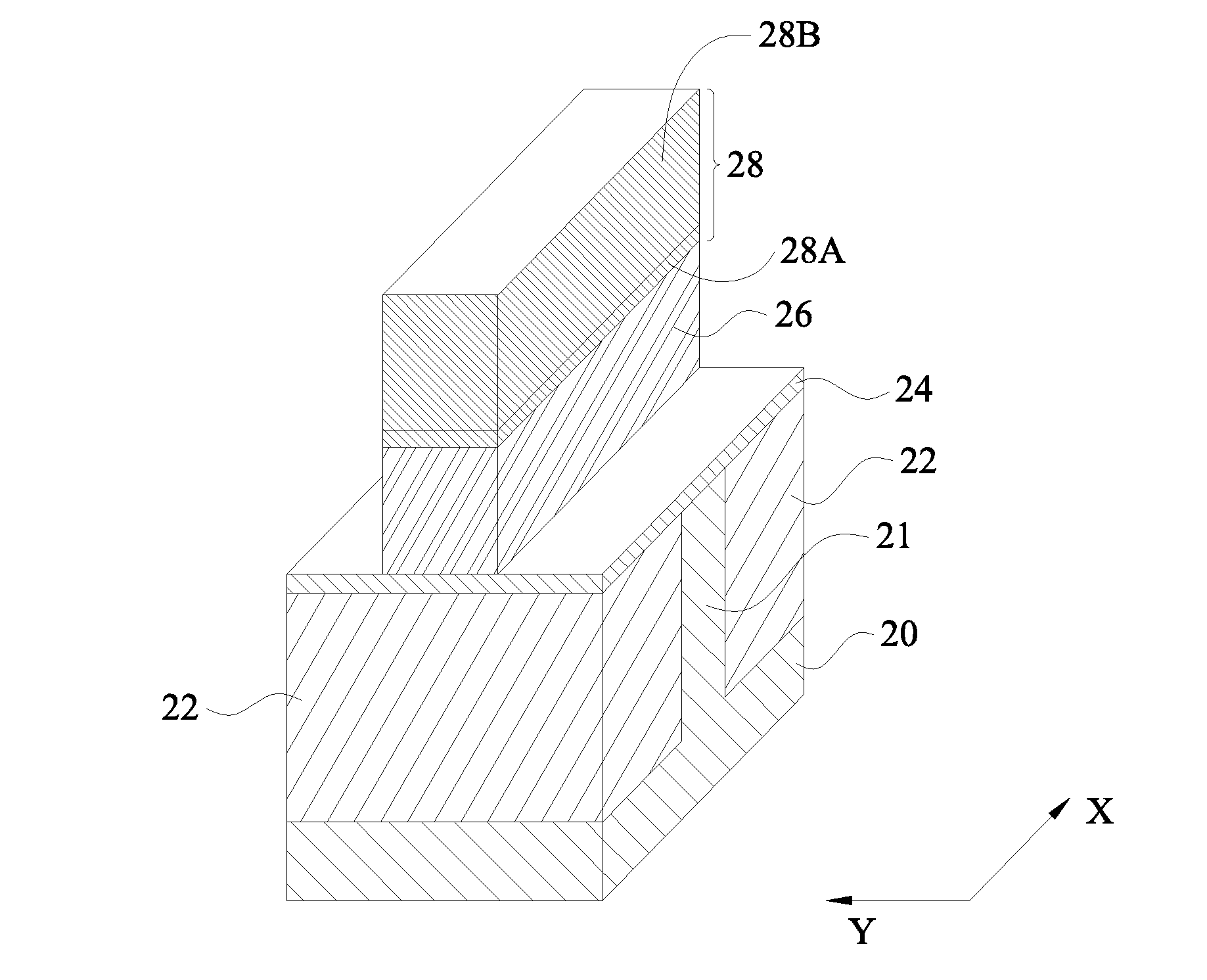
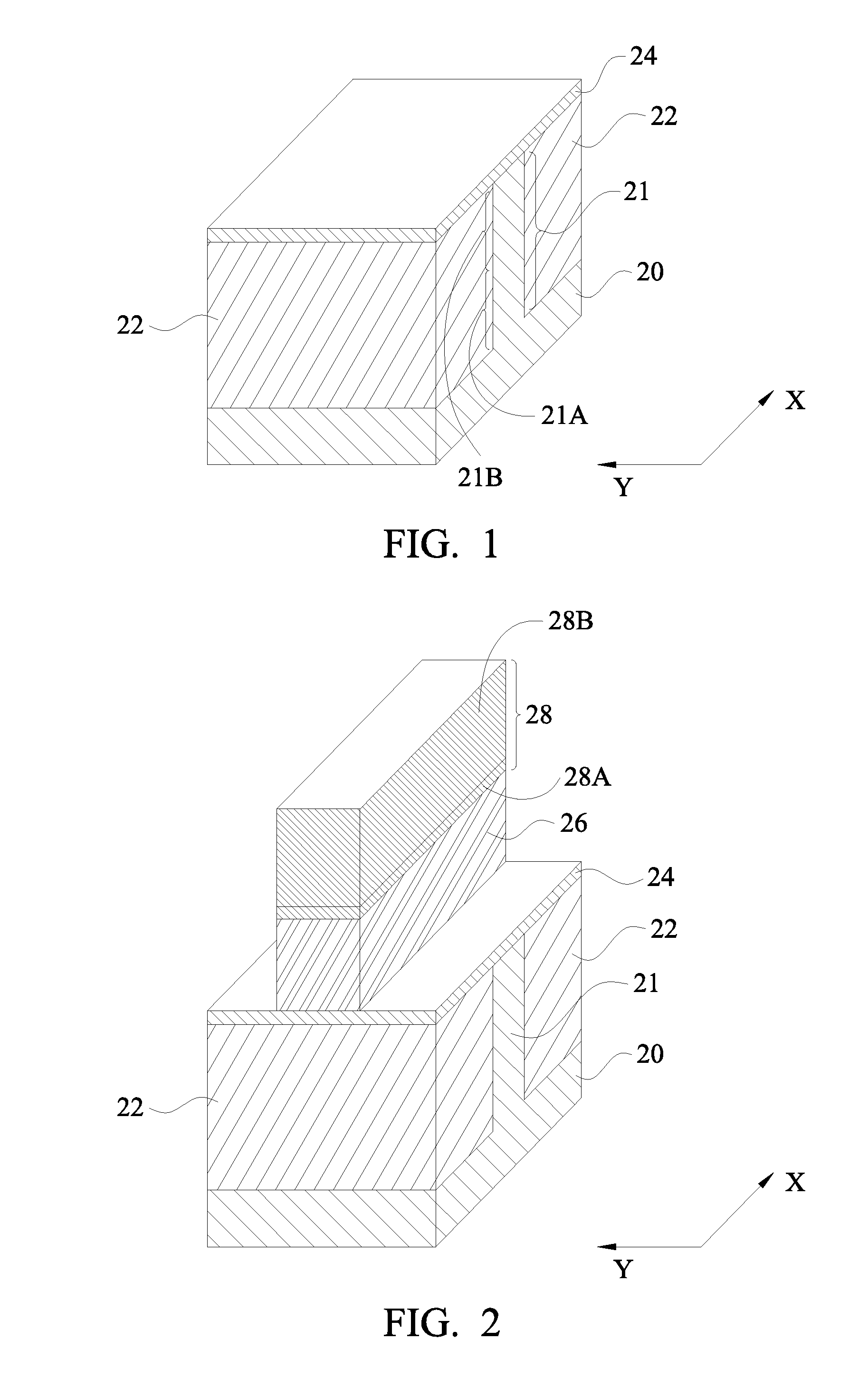
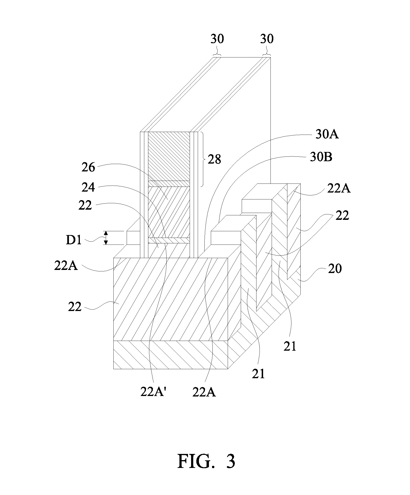
A method includes forming a semiconductor fin over top surfaces of insulation regions, and forming a gate stack on a top surface and sidewalls of a middle portion of the semiconductor fin. The insulation regions include first portions overlapped by the gate stack, and second portions misaligned from the gate stack. An end portion of the semiconductor fin is etched to form a recess located between the second portions of the insulation regions. An epitaxy is performed to grow a source / drain region from the recess. After the epitaxy, a recessing is performed to recess the second portions of the insulation regions, with the second portions of the insulation regions having first top surfaces after the first recessing. A dielectric mask layer is formed on the first top surfaces of the second portions of the insulation regions. The dielectric mask layer further extends on a sidewall of the gate stack.

Description

PRIORITY CLAIM[0001]This application is a continuation-in-part application of the following commonly-assigned U.S. Patent application: application Ser. No. 13 / 673,717, filed Nov. 9, 2012, and entitled “Fin Recess Last Process for FinFET Fabrication;” which application is hereby incorporated herein by reference.BACKGROUND[0002]With the increasing down-scaling of integrated circuits and increasingly demanding requirements to the speed of integrated circuits, transistors need to have higher drive currents with smaller dimensions. Fin Field-Effect Transistors (FinFETs) were thus developed. FinFETs have increased channel widths. The increase in the channel widths is achieved by forming channels that include portions on the sidewalls of semiconductor fins and portions on the top surfaces of the semiconductor fins. Since the drive currents of transistors are proportional to the channel widths, the drive currents of the FinFETs are increased.[0003]In an existing FinFET formation process, Sh...

Claims


Application Information

Patent Timeline
Patent Type & Authority Applications(United States)
IPC IPC(8): H01L29/66H01L27/088H01L21/762
CPCH01L29/78H01L27/0886H01L21/76224H01L29/66795H01L29/66545
Inventor CHING, KUO-CHENGCHEN, GUAN-LIN
Owner TAIWAN SEMICON MFG CO LTD
Learn More