
Automatic driving control system

a control system and automatic technology, applied in the direction of process and machine control, distance measurement, instruments, etc., can solve the problems of discontinuous control, difficult to perform smooth control, and adverse effects on control robustness,

Inactive Publication Date: 2014-10-16
HYUNDAI MOBIS CO LTD
View PDF24 Cites 17 Cited by
  • Summary
  • Abstract
  • Description
  • Claims
  • Application Information

AI Technical Summary

Benefits of technology

The present invention is an automatic driving control system that uses a navigation system to obtain shape information about the road ahead during long periods of autonomous driving. This system then calculates the optimum speed for the vehicle to safely and comfortably drive on curved roads. The technical effect of this invention is that it allows for the vehicle to automatically adjust its speed to the most efficient level for various driving conditions, improving safety and comfort for the driver.

Problems solved by technology

Unfortunately, in the conventional method of controlling the speed on the curved road, since speed control is mostly performed using a point requiring the largest deceleration among curvatures of the road ahead, it may be difficult to perform smooth control in consideration of a comfortable ride, and discontinuous control may be performed.
Most existing technologies use a uniform acceleration required to decelerate the speed, and since the uniform acceleration is different from a physical or actual control input, a comfortable ride, control accuracy, and control robustness may be adversely affected.
In some conventional technologies, since a point of time when deceleration control is performed is not clear, a problem of excessive or insufficient deceleration control may be caused for the curved road ahead.
Since vehicle acceleration for smooth speed control is not sufficiently considered in most cases, the comfortable ride may be decreased, and it may be difficult to obey an optimum speed.

Method used


Image

  • Automatic driving control system
  • Automatic driving control system
  • Automatic driving control system

Examples


Embodiment Construction

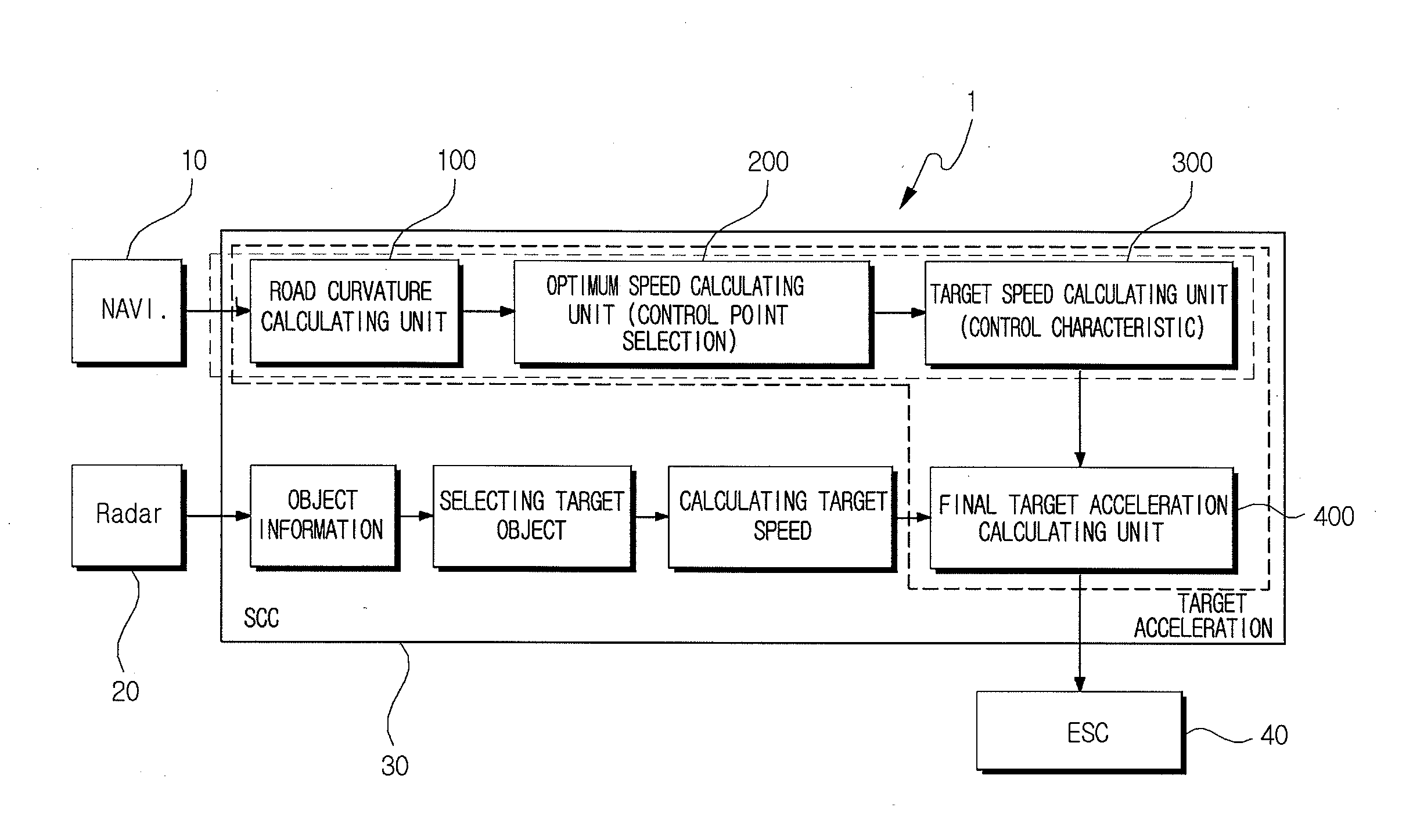
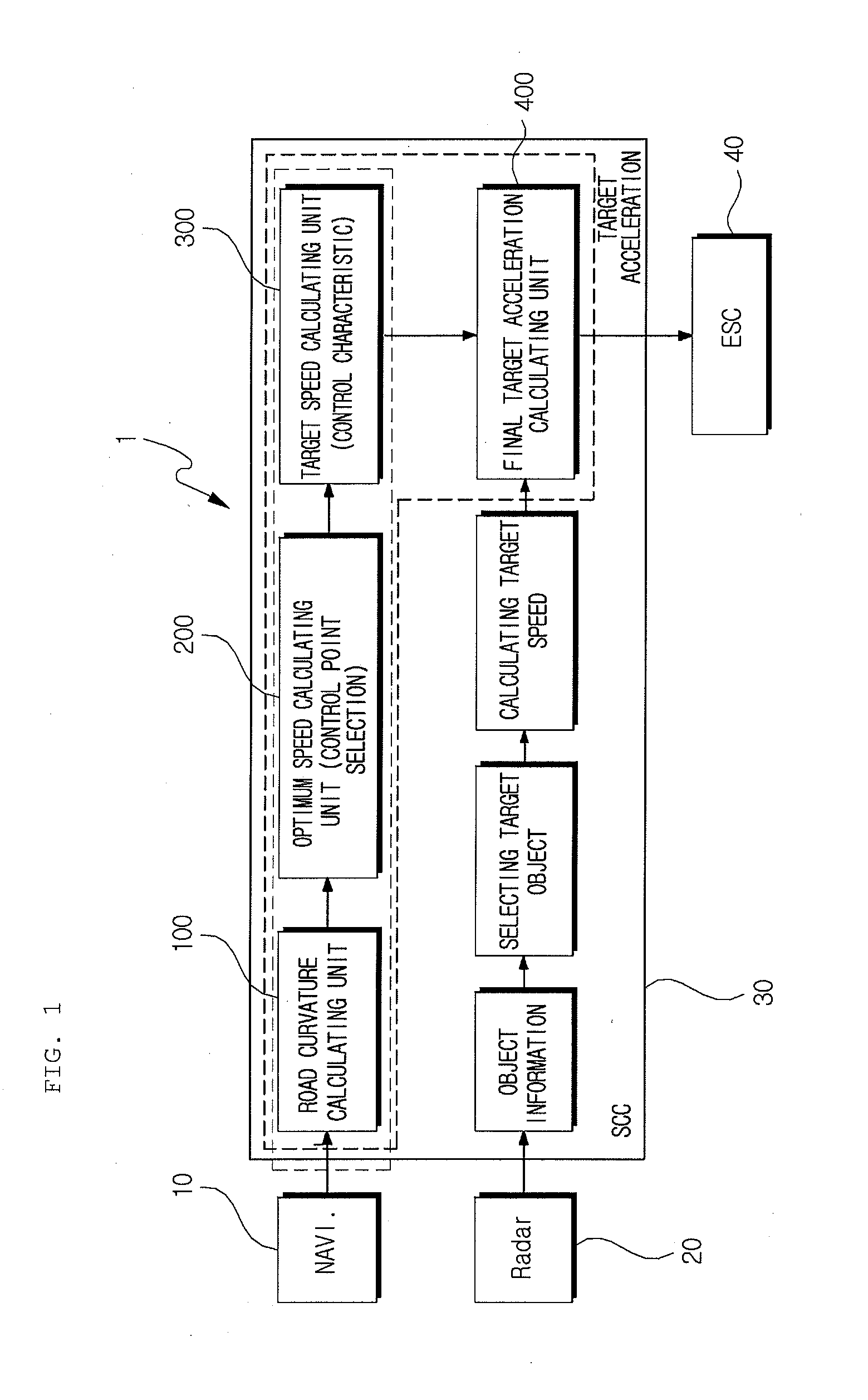
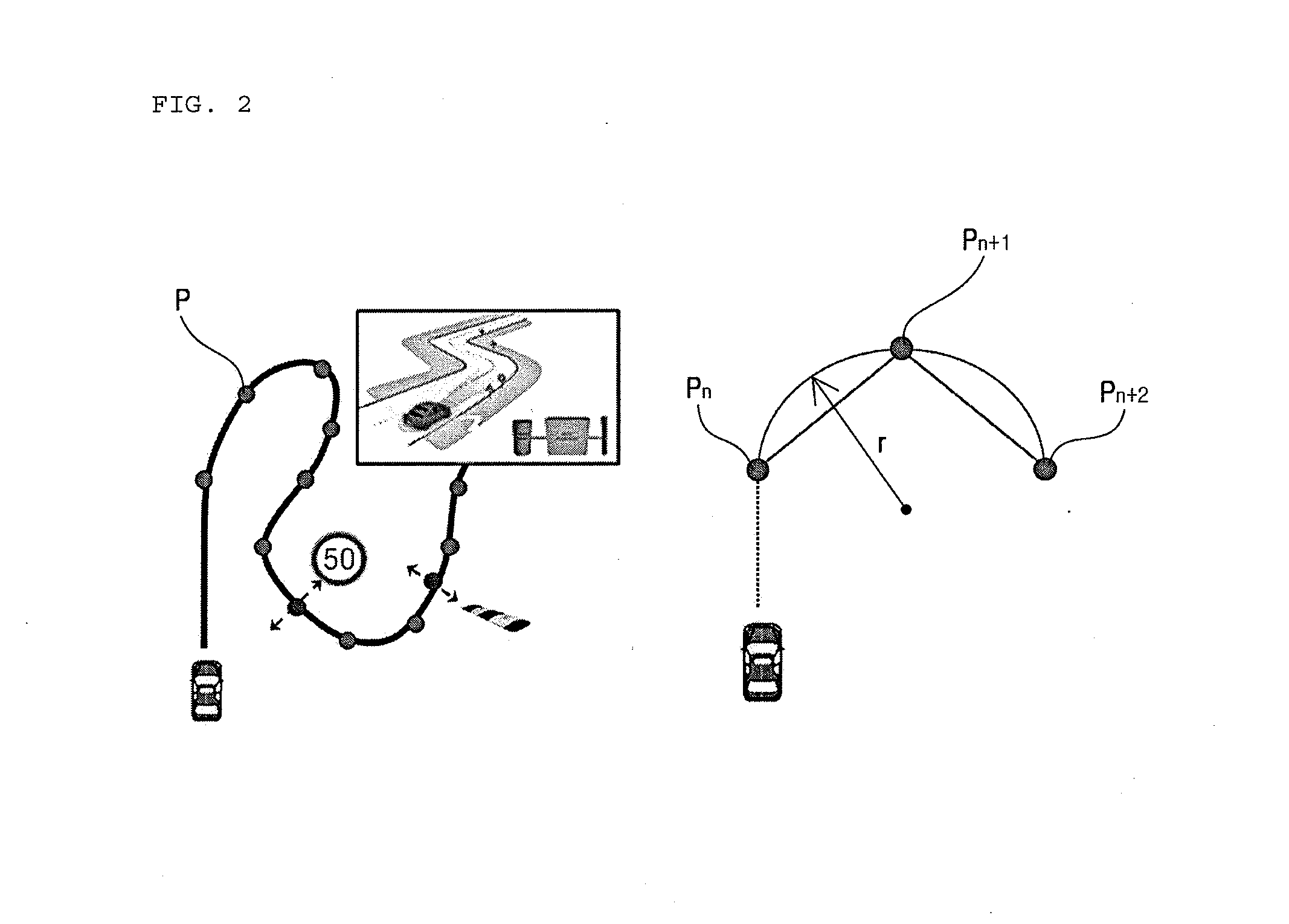
[0033]Hereinafter, exemplary embodiments of the present invention will be described in detail with reference to the accompanying drawings. It should be noted that throughout the accompanying drawings, the same components are assigned the same reference numerals even in different drawings. The exemplary embodiments of the present invention will now be described, but the technical spirit of the present invention is not limited or restricted thereto. Therefore, it should be appreciated that those skilled in the art can variously change and modify these embodiments.

[0034]FIG. 1 is an overall configuration diagram of an automatic driving control system according to an exemplary embodiment of the present invention, FIG. 2 is a diagram for describing a method of calculating a radius of curvature of a road ahead, FIG. 3 is a graph for describing a method of selecting a control position, FIG. 4 is a graph for describing an out of range excluded from a control target among optimum speeds of t...


PUM


Abstract

Disclosed is an automatic driving control system including a road curvature calculating unit that receives shape information of a road ahead from a navigation to calculate curvatures of the road ahead, an optimum speed calculating unit that calculates optimum speeds on the basis of the curvatures of the road calculated by the road curvature calculating unit and selects speed control points, and a target acceleration calculating unit that receives information from the optimum speed calculating unit and calculates a target acceleration on the basis of the calculated optimum speeds and a current speed of a vehicle.

Description

CROSS-REFERENCE TO RELATED APPLICATIONS[0001]This application claims priority to and the benefit of Korean Patent Application No. 10-2013-0040039 filed in the Korean Intellectual Property Office on Apr. 11, 2013, the entire contents of which are incorporated herein by reference.TECHNICAL FIELD[0002]The present invention relates to an automatic driving control system, and more particularly, to an automatic driving control system with which it is possible to automatically control the speed of the vehicle to the optimum speed by obtaining the shape information of the road ahead from the navigation 10 during longitudinal autonomous driving to calculate the optimum speed for allowing the vehicle to drive on the curved road comfortably and safely.BACKGROUND ART[0003]In recent years, the market of products for performing automatic driving control of a vehicle that automatically control driving in order to provide convenience to a driver tends to be gradually extended. For this reason, the ...

Claims


Application Information

Patent Timeline
Patent Type & Authority Applications(United States)
IPC IPC(8): G05D1/02
CPCG05D1/0223B60W30/18B60W40/06B60W40/072B60W40/105B60W40/109B60W30/143B60W30/18145B60W2720/103B60W2720/106B60W2552/30B60W2556/50B60W30/10B60W30/14
Inventor HAM, JUN HO
Owner HYUNDAI MOBIS CO LTD
Learn More