

Trigger mechanism
- Summary
- Abstract
- Description
- Claims
- Application Information
AI Technical Summary
Benefits of technology
Problems solved by technology
Method used
Image

Examples
Embodiment Construction
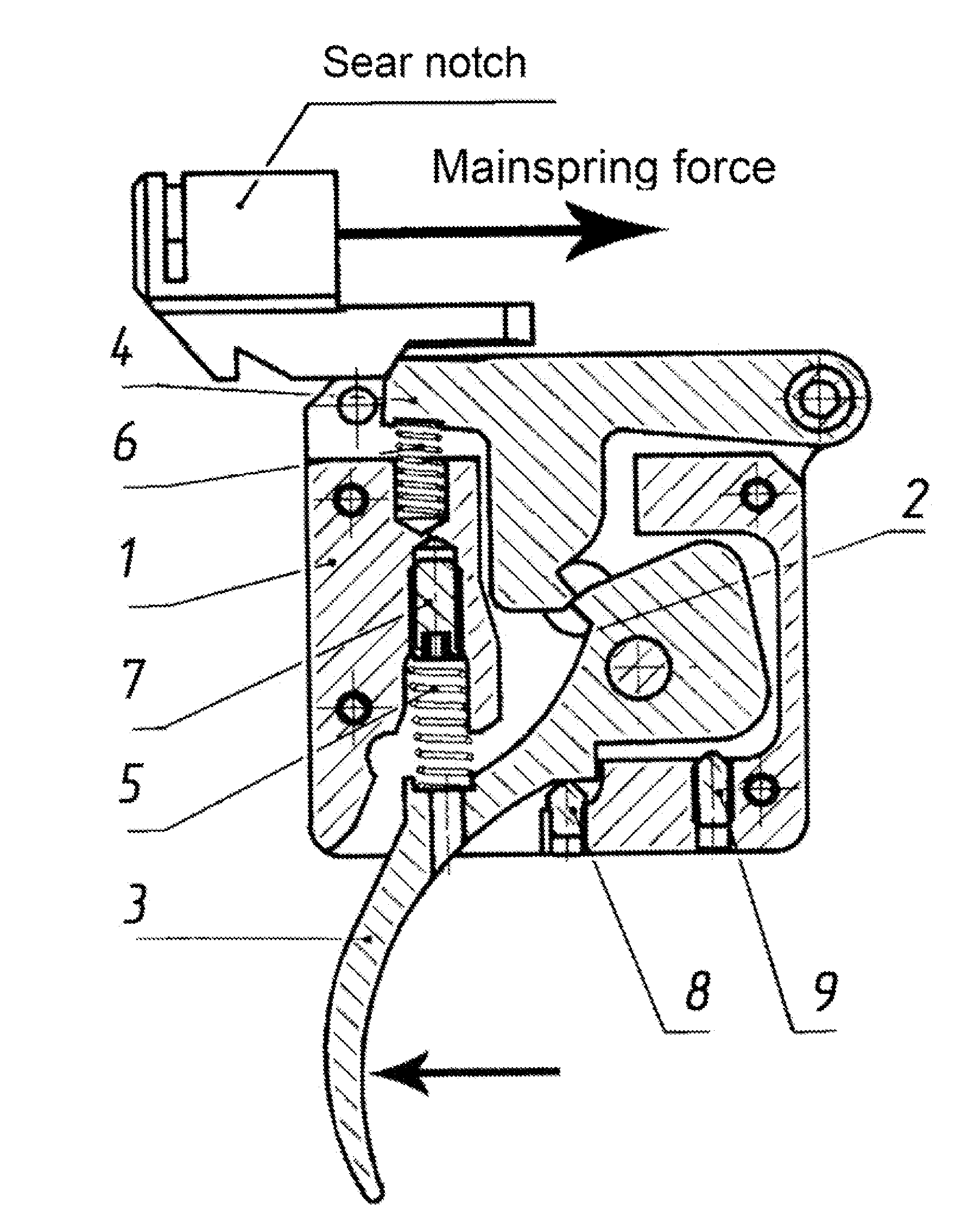
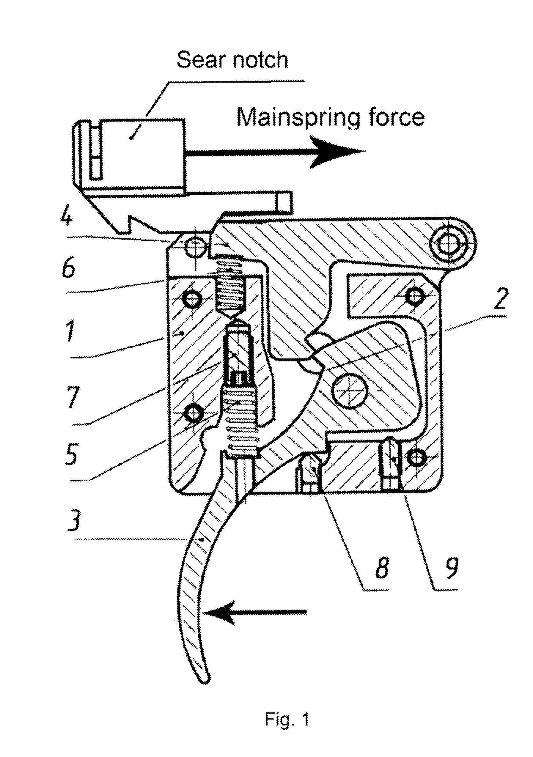
[0017]As shown in FIG. 1, the trigger mechanism in accordance with the preferred embodiment of the invention comprises a body 1 having an aluminum cover (not shown), a technological hole 2, a trigger 3, a sear 4, a triggering spring 5, a sear spring 6, a screw for adjusting triggering 7, a screw for adjusting amount of engagement of the trigger with the sear 8, and a screw for adjusting triggering motion 9.
[0018]Adjustment screws 7, 8, and 9 are mounted in the body base and are oriented vertically at an angle of 90° to the horizontal axis thereof. The sear 4 has a tooth is provided with a tooth which can come into contact with a tooth present on the trigger 3.
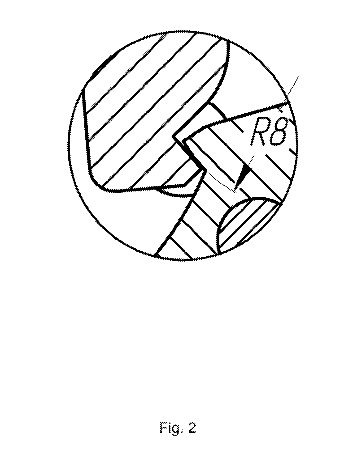
[0019]The trigger tooth surface, which interacts with the sear tooth surface at the time of cocked trigger, is curvilinear, in particular, as shown in FIG. 2, it is a convex arcuated surface of a curvature radius (R) between 5 and 8 mm.
[0020]The amount of engagement is the area of interaction of the teeth surfaces of sear 6 and...
PUM
 Abstract
Description
Claims
Application Information