Tube for a Respirator System

a technology of respirator and tube, which is applied in the field of tubes for respirator systems, can solve the problems of complicated operation and considerable cost, and achieve the effect of low cost, flexible application, and managed and applied flexibly and easily

Active Publication Date: 2014-10-23
HAMILTON MEDICAL AG
View PDF2 Cites 27 Cited by
  • Summary
  • Abstract
  • Description
  • Claims
  • Application Information

AI Technical Summary

Benefits of technology

[0010]It is therefore the object of the present invention to provide a tube for respirator systems which can be produced at low cost, can be managed and applied flexibly and easily, and which makes it possible to provide reliable heating and thus proper ventilation under any application conditions.
[0015]It is advantageous to configure the electrical line of the first and / or second section as a low-impedance, two-wire signal and measurement line and to integrate it into, for example, the wall of the tubing. This facilitates an easy connection of the temperature sensor or other sensors. Additional signal or measurement lines such as data transmission lines can also be present. The signal and measurement lines can be arranged parallel to the heating lines, for example. Alternatively, each of the lines can be (thermally) isolated from each other.
[0016]It is especially advantageous to configure the temperature sensor as a thermocouple and to integrate it into the second connector of the second section, wherein the thermocouple is adapted to bridge the low-impedance, two-wire signal or measurement line, and wherein a connection in the second connector of the second section is adapted to bridge the high-impedance heating wire line. This results in an especially simple structure of the second section, which can be easily turned around so that the tube can assume its other configuration. The integration of the thermocouple into the connector means that it is possible to select the optimal point for measuring the temperature. The bridging of the electrical connection in the second connector of the second section short-circuits the heating line and thus effectively prevents the second section from being heated when in the second configuration.
[0017]It is also advantageous to form the electrical contacts of the connectors in such a way that they cannot be touched unintentionally from the outside. This prevents the contacts from being short-circuited and thus prevents heat from being produced unintentionally or the signal or measurement line from being rendered nonfunctional. This also eliminates the danger of damage to the electrical contacts almost completely.
[0020]It is especially advantageous to configure the ventilator tubing system as a medical-grade, single-use or disposable article. This takes account of the hygienic requirements in a hospital. For delivery, the entire ventilator tubing system, possibly also with the liquid container of the respiratory humidifier, is shrink-wrapped in a plastic sheet, and after use on a patient, it is removed and replaced. As a result of the flexibility with which the tube according to the invention can be used, the ventilator tubing system is suitable for various applications in neonatology and also for the ventilation of adult patients.

Problems solved by technology

Solutions of this type are complicated to operate; they are also complex and thus lead to considerable cost.

Method used


Image

  • Tube for a Respirator System
  • Tube for a Respirator System
  • Tube for a Respirator System

Examples


Embodiment Construction

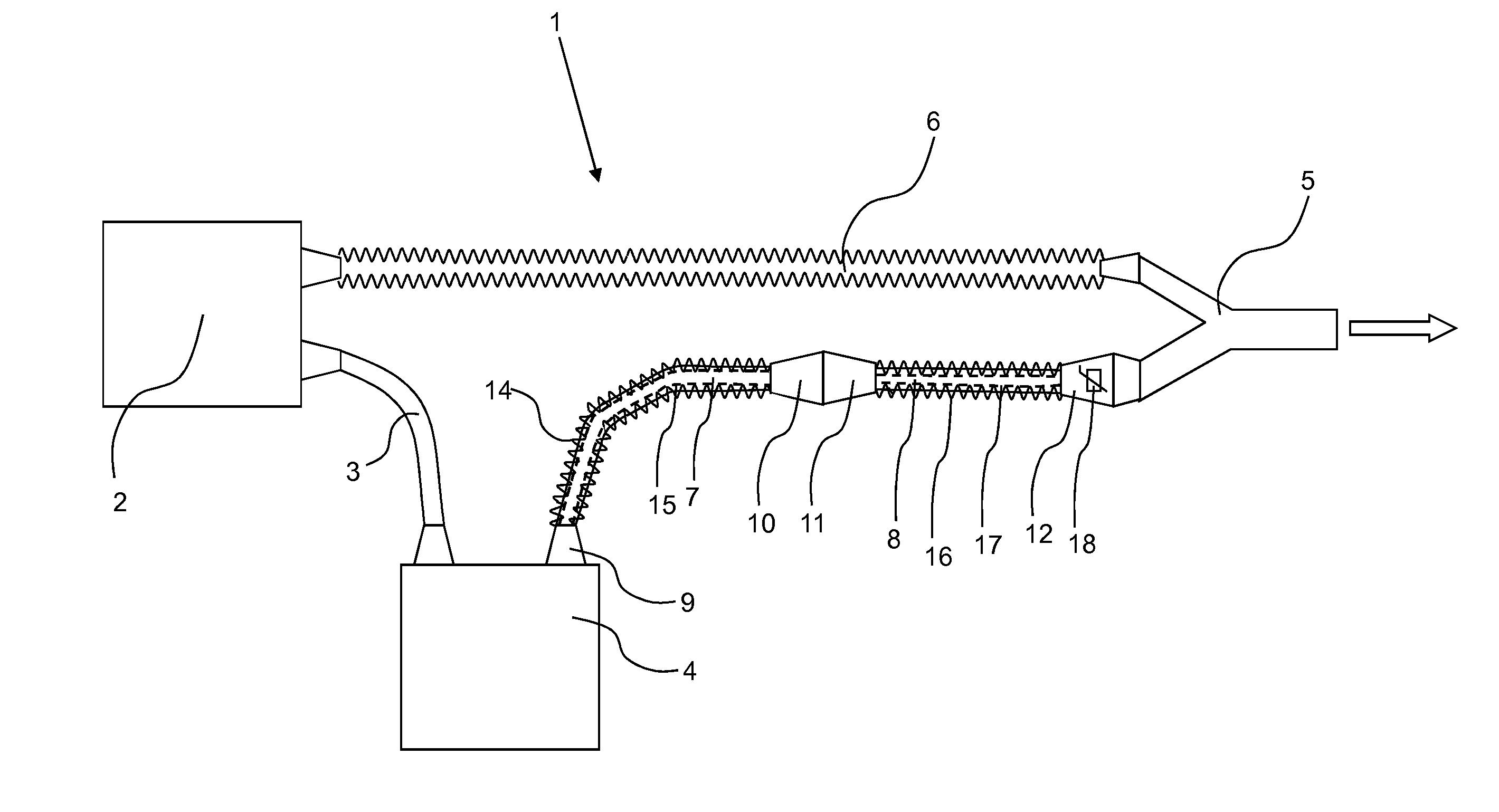
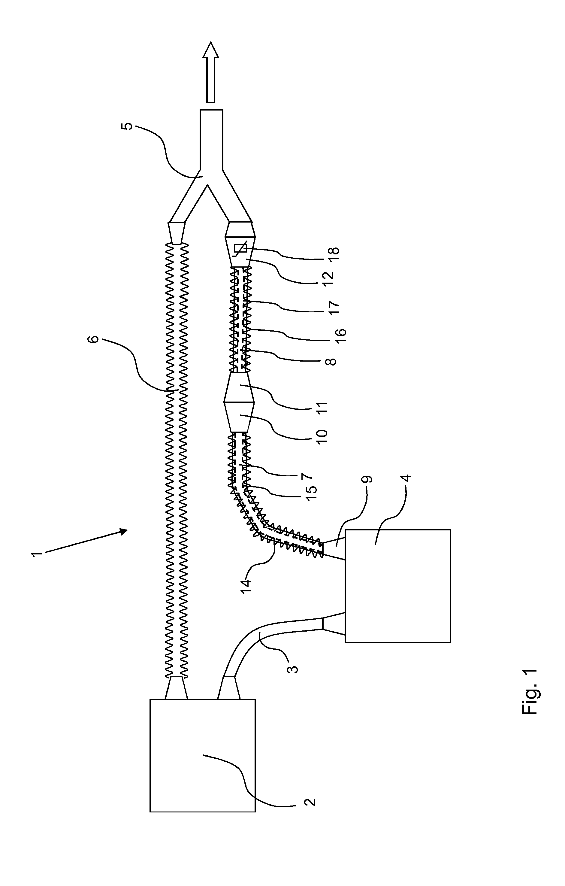
[0026]FIG. 1 shows a schematic diagram of a preferred embodiment of an inventive tube, which is used in a respirator system 1. A first inhalation tube 3 connects a respirator device 2 with a respiratory humidifier 4. The respiratory humidifier 4 is connected by the tube according to the invention to a Y-piece 5. The simply structured end of the Y-piece 5 points toward the patient to be ventilated, as indicated by the arrow. Finally, an exhalation tube 6 is arranged between the respirator device 2 and the other end of the Y-piece 5.

[0027]Dry breathing gas is produced in the respirator device 2 by, for example, a blower (not shown), leaves the device through the first inhalation tube 3, and arrives at the respiratory humidifier 4. There the breathing gas is conducted in the known manner into a liquid container (not shown in FIG. 1), where it is heated and humidified by a heated liquid such as distilled water. The heated and humidified breathing gas leaves the respiratory humidifier 4 ...


PUM

PropertyMeasurementUnit
temperatureaaaaaaaaaa
diametersaaaaaaaaaa
diametersaaaaaaaaaa

Abstract

A tube for a ventilation system (1) for newborns is provided with a first section (7) comprising a heating wire (14), an electrical conductor (15), and a first connector (9) and a second connector (10), and with a second section (8) comprising a heating wire (16) extending over at least a certain portion of its length, an electrical line (17) extending over at least a certain portion of its length, and a first connector (11) and a second connector (12), wherein the second section (8) comprises a temperature sensor (18), wherein the electrical and pneumatic connection of the first section (7) with the second section (8) via the connection of the second connector (10) of the first section (7) is achievable by either connecting to the first connector (11) of the second section (8), so that the second section (8) is substantially heatable, or by connecting to the second connector (12) of the second section (8), so that the second section (8) is substantially not heatable.

Description

FIELD OF INVENTION[0001]The present invention pertains to a tube for a respirator system for ventilating patients with breathing gas, especially for a respirator system for newborns.BACKGROUND OF THE INVENTION[0002]During the mechanical ventilation of patients on an intensive-care ward, for example, the patient to be ventilated is connected pneumatically to the ventilation device by means of a breathing tube system. Because the breathing gas which is delivered to the patient must be adjusted with respect to temperature and humidity to the physiological needs of the patient, a respiratory humidifier is arranged in the inhalation or inspiration tube to heat and humidify the breathing gas. The respiratory humidifier comprises a liquid container filled with distilled water in the usual manner; the inhalation gas is conducted through this container, and its moisture content is thus increased.[0003]To prevent moisture from condensing inside the breathing tube system, the inhalation tube a...

Claims


Application Information

Patent Timeline
Patent Type & Authority Applications(United States)
IPC IPC(8): A61M16/10G01K13/02A61M16/16A61M16/08A61M16/00
CPCA61M16/1095A61M16/0875A61M16/0816A61M16/0003G01K2013/024A61M16/0051A61M16/0057G01K13/02A61M16/16A61M16/08A61M16/1075A61M2205/3368A61M16/109A61M16/0833A61M16/021G01K13/024
Inventor BUECHI, RUDOLFMAEDER, MARCZOLKOS, AXEL
Owner HAMILTON MEDICAL AG
Why Eureka
Try Eureka