

Method and apparatus for creating a dynamically reconfigurable energy storage device
a technology of energy storage device and dynamic reconfiguration, which is applied in the direction of electrochemical generator, parallel/serial switching, secondary cell servicing/maintenance, etc., can solve the problems of parasitic loss, internal discharge, and unnecessary power level overheads required to serve certain applications, and the complexity of the system provided by dc-dc converters
Active Publication Date: 2014-10-23
GLX POWER SYST INC
View PDF1 Cites 133 Cited by
- Summary
- Abstract
- Description
- Claims
- Application Information
AI Technical Summary
Benefits of technology
The present invention is a system for creating a dynamically reconfigurable energy source. The system includes hardware and software components. The hardware includes individual energy modules, such as battery cells, sensors, and control units, which can be connected in different configurations to achieve different functions. The software controls the hardware and allows for real-time management, monitoring, and control of the energy modules. The system can be used for charging and powering various devices, and it provides greater flexibility, functionality, and control than traditional power electronics-based products.
Problems solved by technology
Unfortunately, providing the DC-DC converter adds to the complexity of the system.
DC-DC converters may also provide unnecessary power losses and / or additional overhead requirements in the balance of system.
Another concern associated with cell life and battery management systems is parasitic loss, internal discharge and unnecessary power level overheads required to serve certain applications.
Complicated circuitry at each cell is inherently less reliable.
If many connections are required, the connectors present electrical shock safety issues.
If the connectors are heavy, then they may be unsuitable for aerospace, spacecraft, and other portable applications.
Addressing safety concerns, regulatory compliance and emergency management procedures may also require additional monitoring, control and safety switches introducing additional componentry, failure points and cost.
Method used
View moreImage
Smart ImageViewing Examples

Examples
example
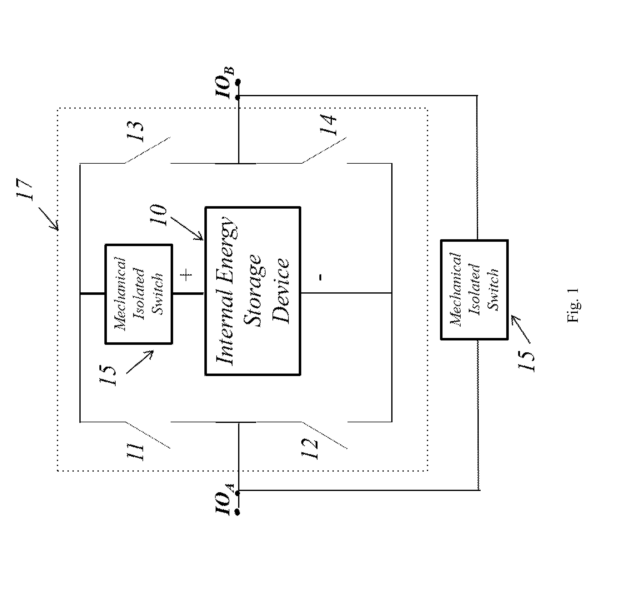
[0143]If there is a Group Controller with ‘A’ number of cells in its group, we can denote it as:
Login to View More PUM
| Property | Measurement | Unit |
|---|---|---|
| voltages | aaaaa | aaaaa |
| voltages | aaaaa | aaaaa |
| voltages | aaaaa | aaaaa |
Abstract
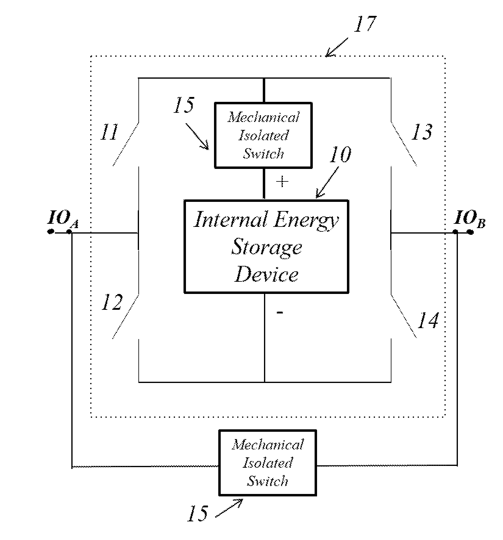
A method and apparatus of creating a dynamically reconfigurable energy source comprised of individual, isolated, controllable energy modules, supported by software to measure and manage the energy modules and facilitate the reconfiguration, where the platform consisting of hardware, based upon an inverted H-Bridge circuitry, in combination with software which allows for real-time management, control, and configuration of the modules and uses a combination of software algorithms and localized electronic switches, to achieve a performance and functionality of the invention matching, or exceeding, traditional large, heavy, and expensive power electronics-based products used for charging, energy storage management, power inverting, and motor or load control.
Description
BACKGROUND OF THE INVENTION[0001]The present invention is related to a power management system for use in connection with battery cells, which allow the cells and batteries to be turned into variable energy storage sources, which can be used in devices, such as for example, electric vehicles or grid storage. More specifically, the present invention is a platform, which uses a switch nodule having 2n+2 switches, where n is 1 or more and based upon the number of energy modules, and includes switch modules based upon inverted H-Bridge circuitry, as well as a switch module having an alternating polarity, which will be discussed further later, in combination with software which allows for real-time monitoring, management, control, and configuration of energy modules.[0002]Battery-Powered Applications include either an AC-DC converter that converts an AC source such as a 120V, 60 Hz wall outlet, to the appropriate DC level to charge the battery, or a DC-DC converter to convert a DC power ...
Claims
Login to View More Application Information
Patent Timeline
 Patent Type & AuthorityApplications(United States)
IPC IPC(8): H01M10/42H02J7/00
CPCH01M10/4257H01M2010/4271H02J7/0054H02J7/0021H02J7/0024H02J7/342Y02T10/70Y02E60/10H02J7/0016
InventorVO, TOM V.GRAS, COURTNEY A.KRISTENSEN, KENTMAHMODICHERATI, SAM
OwnerGLX POWER SYST INC