Current switching device with igct

a current switching device and igct technology, applied in electronic switching, pulse technique, electric apparatus, etc., can solve the problems of reduced gate circuit impedance, limited gate voltage, and subject to practical limits

Active Publication Date: 2014-10-23
HITACHI ENERGY SWITZERLAND AG
View PDF3 Cites 3 Cited by
  • Summary
  • Abstract
  • Description
  • Claims
  • Application Information

AI Technical Summary

Problems solved by technology

In a known gate unit, the available gate voltage is limited by the gate-commuted thyristor (GCT) technology, for example by the avalanche or breakdown voltage of the diode between the gate and the cathode.
Alternatively, the impedance of the gate circuit may be decreased, which is also possible, but may be subjected to practical limits such as the lateral extension of the silicon wafer, the insulation specifications, cost, etc.

Method used


Image

  • Current switching device with igct
  • Current switching device with igct
  • Current switching device with igct

Examples


Embodiment Construction

[0016]Exemplary embodiments of the present disclosure provide a reliable and fast capability of switching an IGCT, without modifying the IGCT itself.

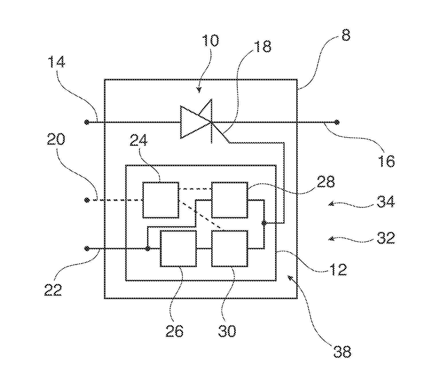
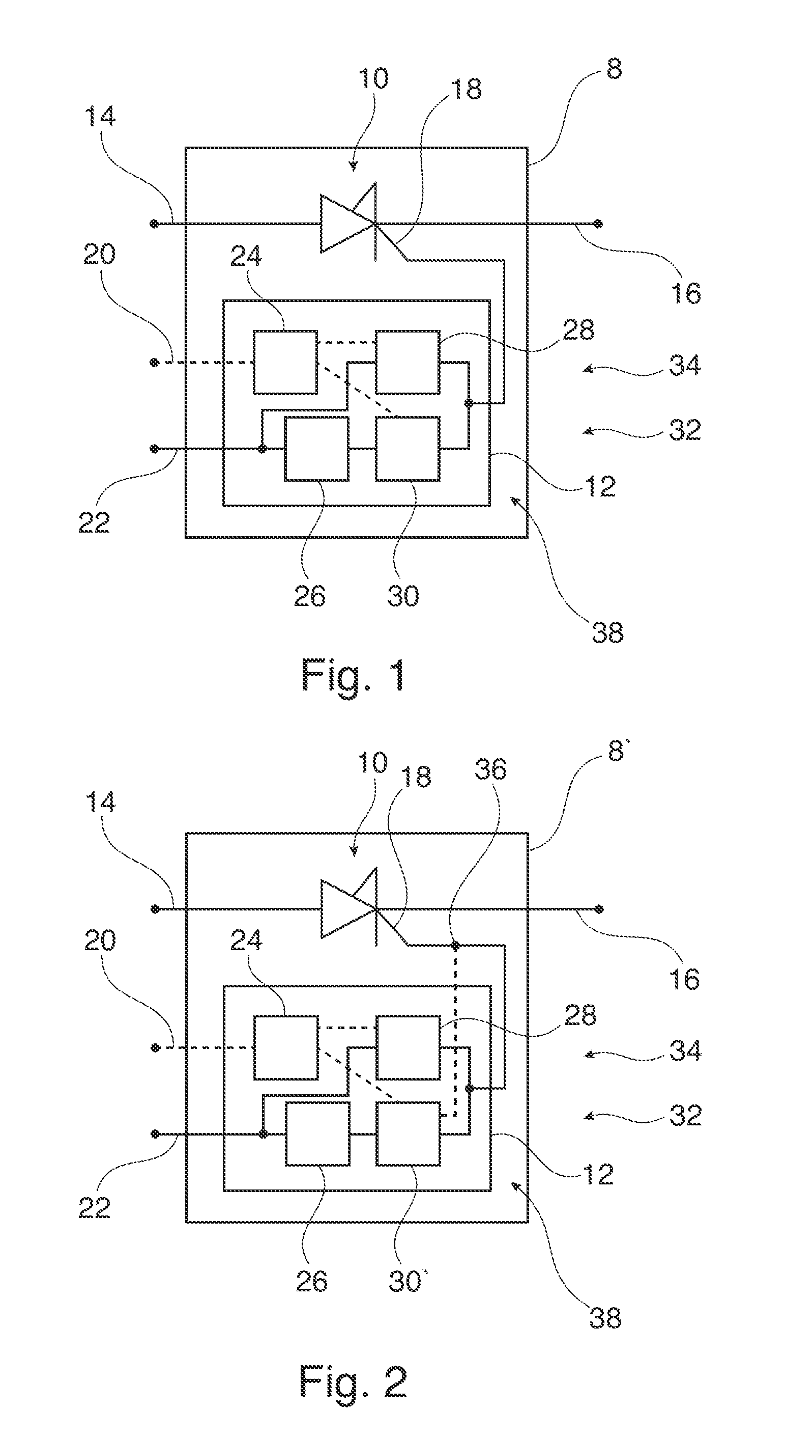
[0017]According to an exemplary embodiment of the present disclosure, a current switching device may be seen as a module including an IGCT and its control, a gate unit. The current switching device and for example the IGCT may be adapted for switching high currents, e.g., current above 100 A or even above 1,000 A and / or medium voltages above 1,000 V or 5,000 V.

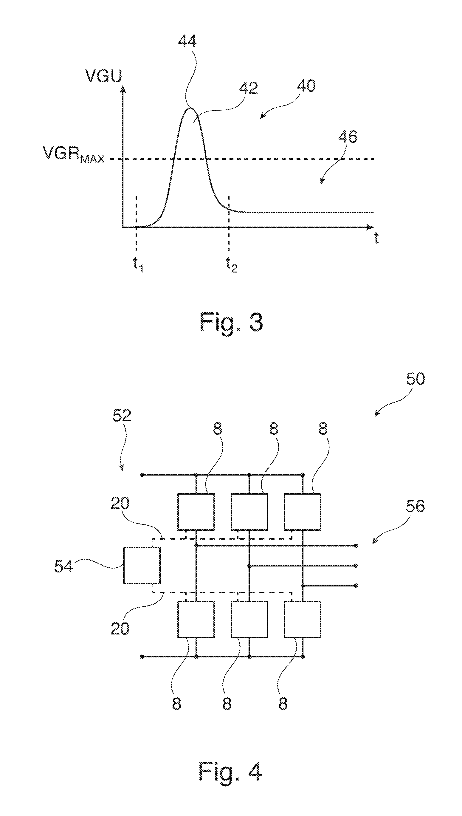
[0018]According to an exemplary embodiment of the present disclosure, the current switching device includes an IGCT with an anode, a cathode and a gate, wherein a current between the anode and the cathode is interruptible by applying a switch-off voltage to the gate; and a gate unit for generating the switch-off voltage, the gate unit and a connection of the gate unit to the gate establishing a gate circuit having a stray impedance. The gate unit is adapted for generating a spiked...


PUM


Abstract

An exemplary current switching device includes an integrated gate-commutated thyristor with an anode, a cathode, and a gate, wherein a current between the anode and the cathode is interruptible by applying a switch-off voltage to the gate; and a gate unit for generating the switch-off voltage. The gate unit and a connection of the gate unit to the gate establish a gate zcircuit having a stray impedance. The gate unit is adapted for generating a spiked switch-off voltage with a maximum above a breakdown voltage (VGRMAX) between the cathode and the gate, such that the switch-off voltage at the gate stays below the breakdown voltage (VGRMAX) due to the stray impedance of the gate circuit.

Description

[0001]RELATED APPLICATION(S)[0002]This application claims priority under 35 U.S.C. §119 to European Patent Application No. 13164553.3 filed in Europe on Apr. 19, 2013, the content of which is hereby incorporated by reference in its entirety.FIELD[0003]The disclosure relates to the field of high power electronics, and particularly to a current switching device, an inverter, and a method for switching an integrated gate-commutated thyristor (IGCT).BACKGROUND INFORMATION[0004]IGCTs are semiconductor switching devices that, for example, are used in inverters and other high power electronics devices due to their fast switching behaviour and their low switching losses. An IGCT in the conducting state may be switched off by applying a voltage to the gate of the IGCT. After that, a current between the anode and the cathode is blocked, and the IGCT remains in the blocked state until a negative voltage is applied to the gate again.[0005]Usually, a gate unit is used to control the switching an...

Claims


Application Information

Patent Timeline
Patent Type & Authority Applications(United States)
IPC IPC(8): H03K17/732
CPCH03K17/732H03K17/0412
Inventor WIKSTROM, TOBIAS
Owner HITACHI ENERGY SWITZERLAND AG
Why Eureka
Try Eureka