Power monitor for optical fiber using background scattering

a technology of optical fiber and background scattering, applied in the field of optical power monitors, can solve the problems of high cost of power measuring equipment, limited fiber optical system, and inability to match the sampling ratio across all transversal modes of the fiber

Inactive Publication Date: 2014-10-23
LUMENTUM OPERATIONS LLC
View PDF2 Cites 56 Cited by
  • Summary
  • Abstract
  • Description
  • Claims
  • Application Information

AI Technical Summary

Benefits of technology

[0011]stripping light from the cladding to ensure only Rayleigh scattered light is measured by the photo detector; and

Problems solved by technology

Indirectly measuring optical power in a fiber laser system, i.e. without putting a power measuring device directly into the optical path, is desirable, because of a lack of accessibility to the measuring point and the high cost of power measuring equipment.
Conventional sampling methods often work reasonably well with low power single-mode (SM) fiber laser systems, but have limitations in fiber optical systems with large-mode-area (LMA) or multi-mode (MM) fibers and high-power fiber laser systems.
One drawback of conventional methods with LMA or MM fibers is that the sampling ratio is not identical across all transversal modes of the fiber.
Moreover, in high-power fiber laser systems, a fuse fiber tap coupler or splice point is not always feasible or desirable, because they might not be able to handle the optical power level or because of the associated penalties on the output power and beam quality.

Method used


Image

  • Power monitor for optical fiber using background scattering
  • Power monitor for optical fiber using background scattering
  • Power monitor for optical fiber using background scattering

Examples


Embodiment Construction

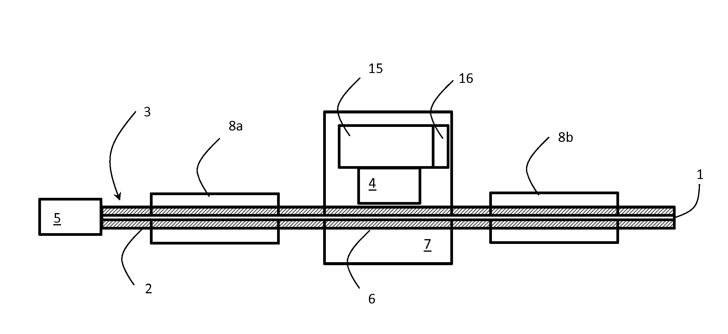
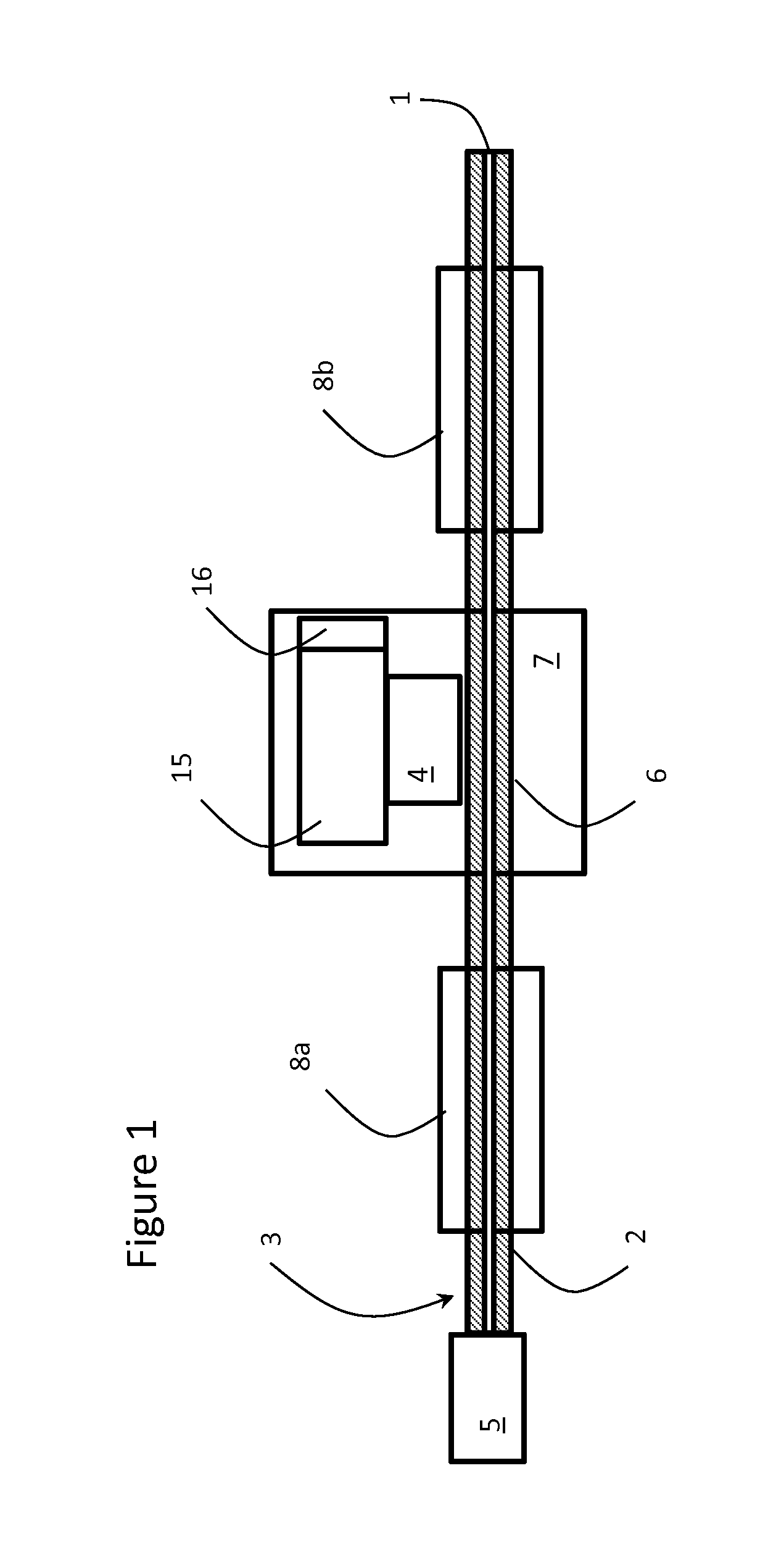
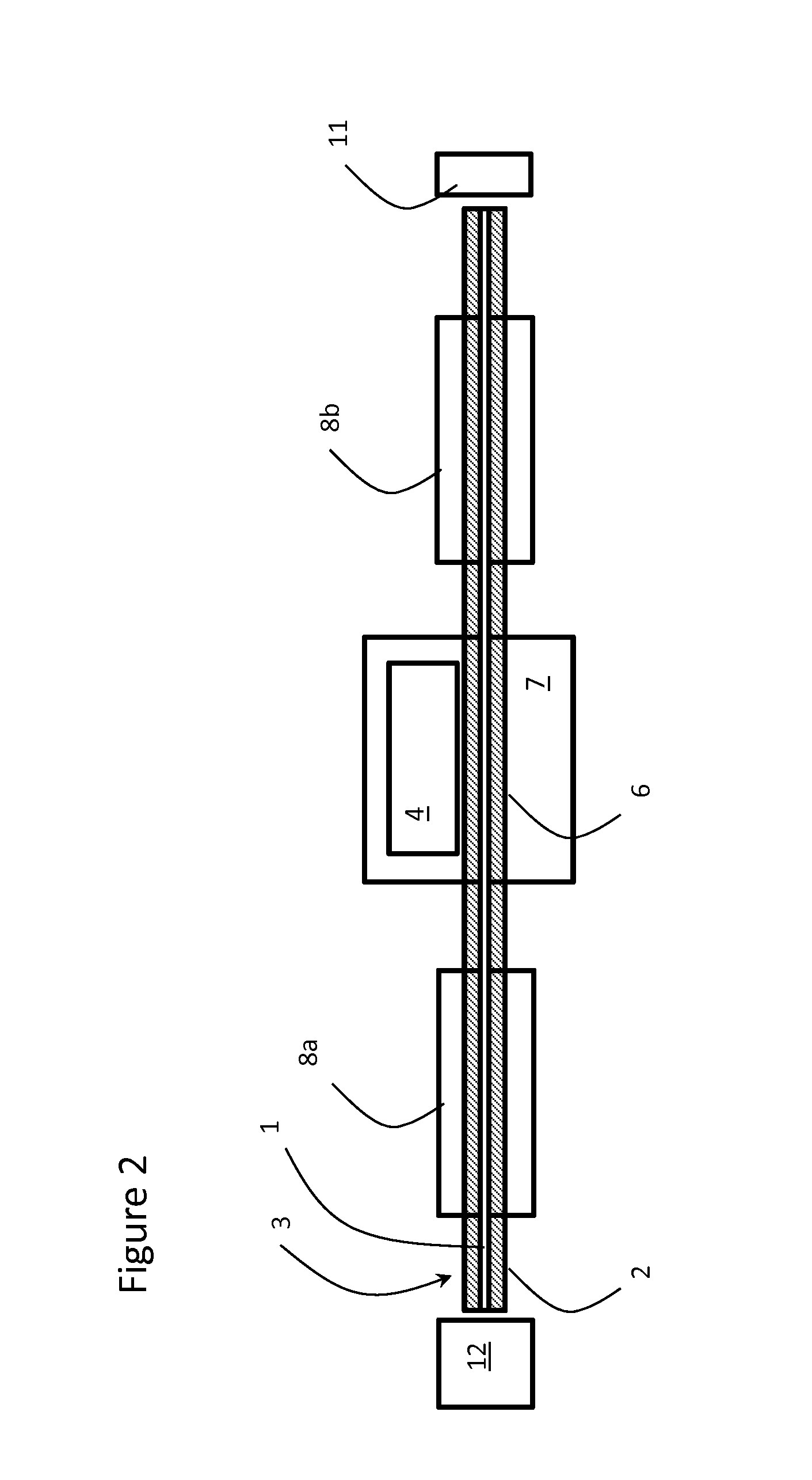
[0018]The method of measuring optical power in the core of an optical fiber in accordance with the present invention utilizes the intrinsic property of background scattering loss of an optical fiber. Background loss of a typical passive fiber core is in the range 0.1 dB / km to 10 dB / km, and the background loss level depends on the fiber manufacturing process and the operating wavelength. 0.1 dB / km loss corresponds to 2.3×10⁻⁸ / mm loss and 10 dB / km loss corresponds to 2.3×10⁻⁶ / mm loss. Several factors contribute to the background loss of the fiber and the primary ones are the absorption from impurities and Rayleigh scattering. Rayleigh scattering scatters a small fraction of optical power out of the fiber from the core. The coefficient of Rayleigh scattering is insensitive to the transversal modes and does not vary in majority of the operating conditions. Thus, the intensity of Rayleigh scattered light from the fiber core is directly proportional to the optical power propagating inside...


PUM


Abstract

An optical power monitoring device includes a photodetector disposed in close proximity to the cladding of an optical fiber for measuring Rayleigh scattered light from the core of the optical fiber. To ensure only Rayleigh scattered light is measured, a cladding stripper is provided to remove any cladding light prior taking a reading with the photodetector.

Description

TECHNICAL FIELD[0001]The present invention relates to an optical power monitor, and in particular to an optical power monitor for detecting Rayleigh scattering from an optical fiber.BACKGROUND OF THE INVENTION[0002]Indirectly measuring optical power in a fiber laser system, i.e. without putting a power measuring device directly into the optical path, is desirable, because of a lack of accessibility to the measuring point and the high cost of power measuring equipment. In order to perform an indirect power measurement, sampling of the optical power in the fiber being measured is required. Sampling of optical power propagating in the core of an optical fiber is commonly done using a fused fiber tap coupler or by detecting the scattered light from a fiber fusion splice location. Conventional sampling methods often work reasonably well with low power single-mode (SM) fiber laser systems, but have limitations in fiber optical systems with large-mode-area (LMA) or multi-mode (MM) fibers a...

Claims


Application Information

Patent Timeline
Patent Type & Authority Applications(United States)
IPC IPC(8): G01J1/42
CPCG01J1/4257G01J1/0271G01J1/0407G01J1/0425G01J1/0295G01J1/1626G01J1/0214G02B6/4286G02B6/4291
Inventor LIAO, KAI-HSIU
Owner LUMENTUM OPERATIONS LLC
Why Eureka
Try Eureka