Access System, Communication Method and Device for Optical Fiber Network

a communication method and optical fiber network technology, applied in the field of communication, can solve the problems of high maintenance cost, difficult to maintain the onus of optical fiber network, high cost, etc., and achieve the effect of reducing maintenance cost and reducing maintenance complexity

Active Publication Date: 2014-10-23
HUAWEI TECH CO LTD
View PDF22 Cites 5 Cited by
  • Summary
  • Abstract
  • Description
  • Claims
  • Application Information

AI Technical Summary

Benefits of technology

[0030]The technical solutions provided in embodiments of the present invention have the following beneficial effects. The customer premises equipment is established, the ONU control plane function, the PON MAC function, and the QoS function on the existing ONU are moved downwards to the established customer premises equipment. After the forgoing functions are removed from the existing ONU, the existing ONU becomes the ONU physical converter and only has a function of converting the PON physical layer frame and the first user side physical layer frame. Therefore, a carrier does not need to maintain the ONU control plane function, the PON MAC function, and the QoS function, which lowers maintenance complexity and greatly reduces maintenance costs.

Problems solved by technology

However, direct fiber to the home requires re-laying out an optical fiber for each home, which has high costs.
Therefore, in the case of massive ONUs on the optical fiber network, it is very difficult to maintain the ONUs on the optical fiber network and a maintenance cost is very high.

Method used


Image

  • Access System, Communication Method and Device for Optical Fiber Network
  • Access System, Communication Method and Device for Optical Fiber Network
  • Access System, Communication Method and Device for Optical Fiber Network

Examples


embodiment 1

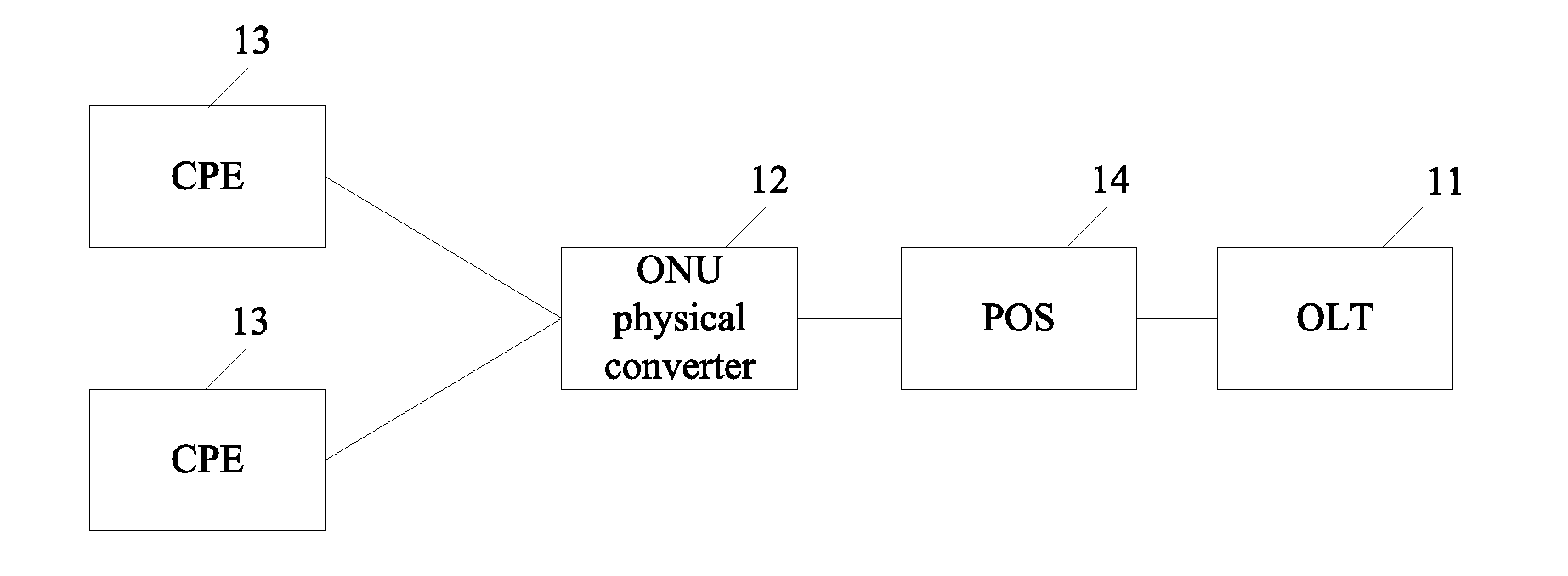
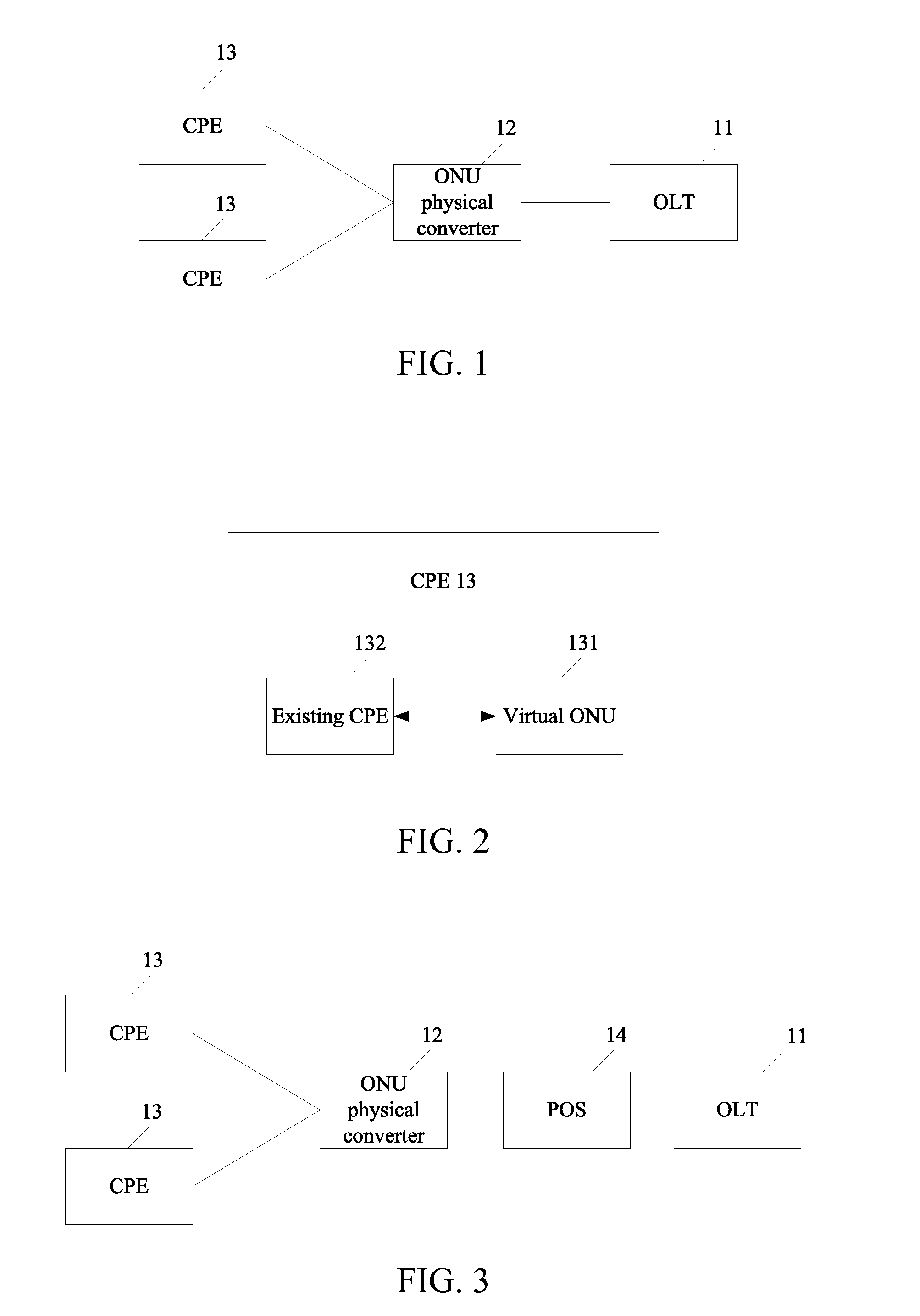
[0052]As shown in FIG. 1, this embodiment provides an access system for an optical fiber network, where the system includes the following. An OLT11 is configured to assign an upstream time slice and a downstream time slice for each customer premises equipment connected to the optical fiber network.

[0053]An ONU physical converter 12 is connected to the OLT11 through an optical fiber, and configured to receive a PON physical layer frame which is sent by the OLT11 through a PON physical signal, convert the PON physical layer frame to a first user side physical layer frame corresponding to a non-PON physical signal, and send the first user side physical layer frame to a customer premises equipment 13 through the non-PON physical signal, or receive a first user side physical layer frame which is sent by the customer premises equipment 13 through the non-PON physical signal, convert the first user side physical layer frame to a PON physical layer frame corresponding to the PON physical si...

embodiment 2

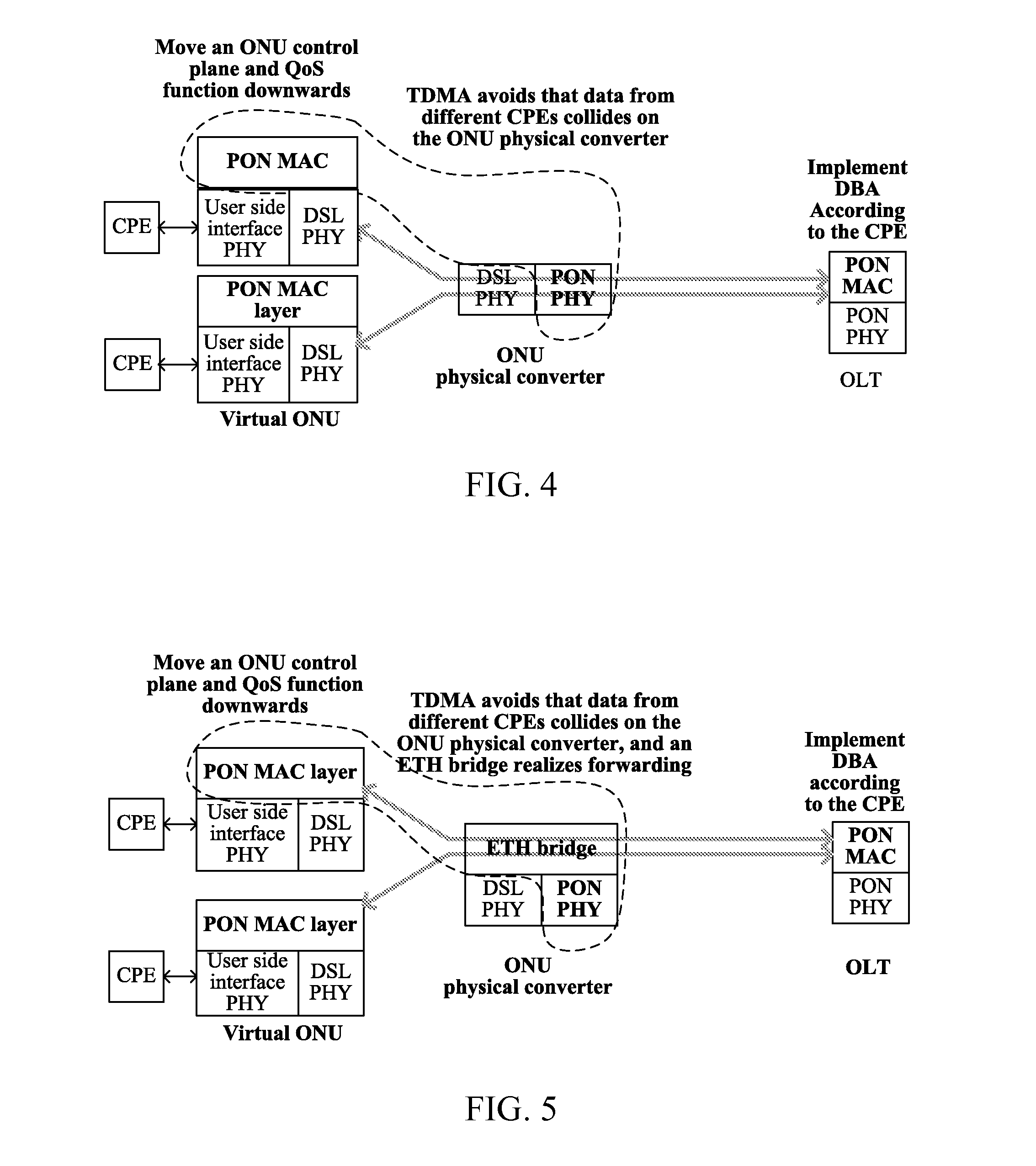
[0066]Based on an access system for an optical fiber network provided in Embodiment 1 and because the system provided in Embodiment 1 makes an innovative improvement on an existing ONU, where a customer premises equipment located on a user side is established, an ONU control plane function, a PON MAC function, and a QoS function on the existing ONU are moved downwards to the customer premises equipment. After the forgoing functions are removed from the existing ONU, the existing ONU becomes an ONU physical converter and only has a function of converting the PON physical layer frame and the first user side physical layer frame. Meantime, the access system provided in Embodiment 1 also makes an improvement on a protocol stack used for communication in the optical fiber network. Therefore, the present invention also makes an improvement on a communication method for the optical fiber network. Embodiment 2 provides an improved communication method.

[0067]Embodiment 2 first describes an i...

embodiment 3

[0121]This embodiment provides a customer premises equipment, where the customer premises equipment is connected to an ONU physical converter through a non-PON optical fiber and is located on a user side, and is configured to realize an ONU control plane function and a PON MAC function, send a first user side physical layer frame to the OLT through the ONU physical converter according to an upstream time slice assigned by an OLT, or receive, according to a downstream time slice assigned by the OLT, a first user side physical layer frame which is sent by the OLT through the ONU physical converter.

[0122]Further, the customer premises equipment is configured to receive a second physical layer parameter which is delivered by the OLT through the ONU physical converter and establish a new communication connection with the ONU physical converter according to the second physical layer parameter delivered by the OLT.

[0123]The customer premises equipment is further configured to the following...


PUM


Abstract

Embodiments of the present invention provide an access system and a communication method for an optical fiber network. A virtual ONU located on a user side is established, and an ONU control plane function, a PON MAC function, and a QoS function on an existing ONU is moved downwards to a virtual ONU. After the forgoing function modules are removed from the existing ONU, the existing ONU becomes an ONU physical converter and only has a function of converting the PON physical layer frame and the first user side physical layer frame.

Description

[0001]This application is a continuation of International Application No. PCT / CN2012 / 079767, filed on Aug. 7, 2012, which is hereby incorporated by reference in its entirety.TECHNICAL FIELD[0002]The present invention relates to the field of communications and, in particular embodiments, to an access system, a communication method and a device for an optical fiber network.BACKGROUND[0003]Because an optical fiber has a higher transmission speed and users have increasingly high requirements on bandwidth, it has become a development trend for an access network to replace a cable with the optical fiber. FTTH (Fiber To The Home) is a future development direction. However, direct fiber to the home requires re-laying out an optical fiber for each home, which has high costs. Therefore, FTTDp (Fiber To Drop / Distribution Point) is still used for a long time. A copper cable (such as a phone twisted pair cable, a cable TV cable, a power cable, or an Ethernet network cable) that has been connecte...

Claims


Application Information

Patent Timeline
Patent Type & Authority Applications(United States)
IPC IPC(8): H04J3/16H04B10/27
CPCH04B10/27H04J3/1652H04Q11/0067H04Q11/0071H04Q2011/0079H04Q2011/0084H04Q2213/1301H04L12/2861H04L12/2885H04Q2011/0064
Inventor ZHENG, RUOBIN
Owner HUAWEI TECH CO LTD
Why Eureka
Try Eureka