

Detection device and image forming apparatus
- Summary
- Abstract
- Description
- Claims
- Application Information
AI Technical Summary
Benefits of technology
Problems solved by technology
Method used
Image

Examples
first embodiment
Apparatus Configuration
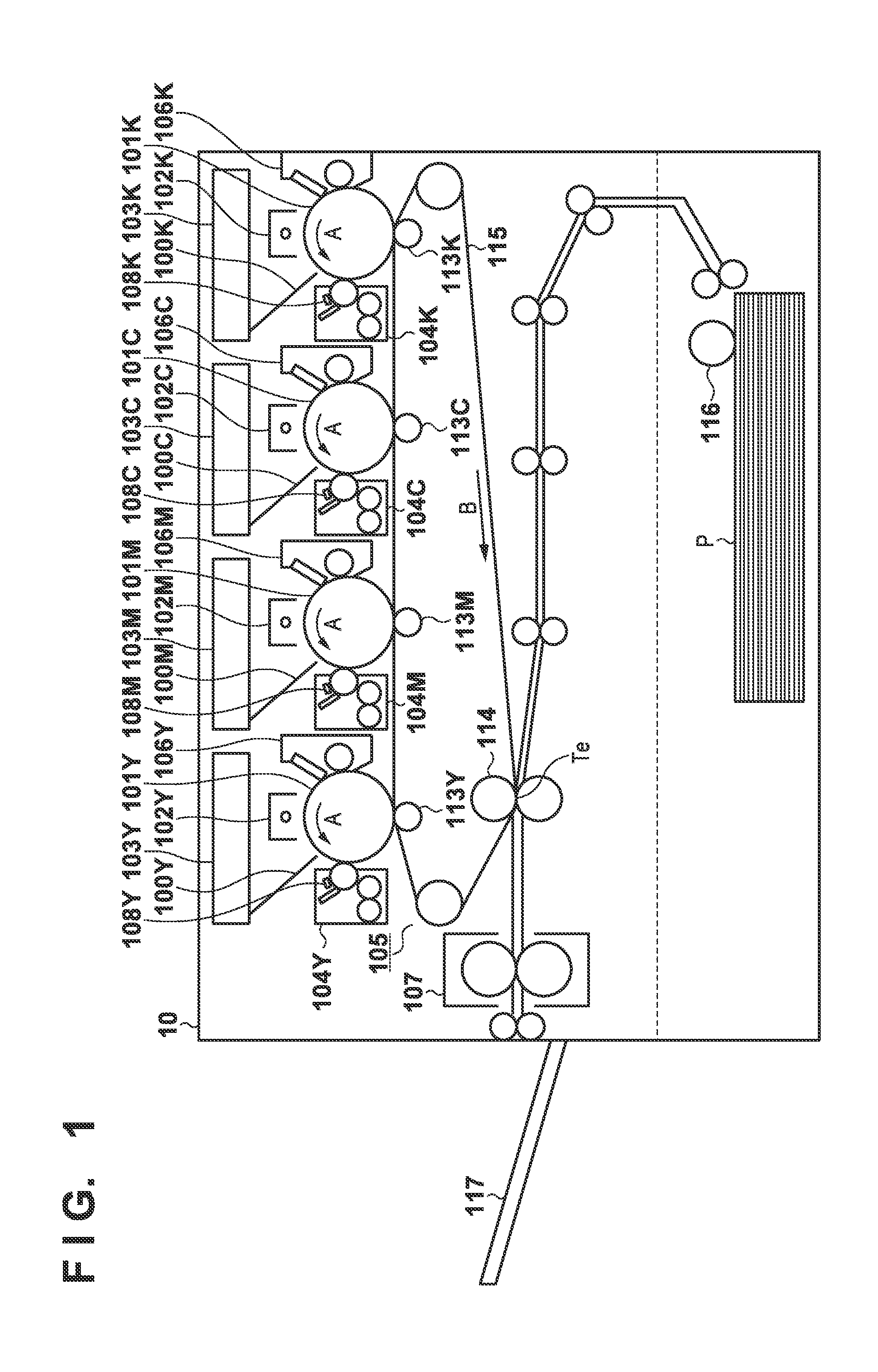
[0043]FIG. 1 is a diagram illustrating the overall configuration of an electrophotographic image forming apparatus.
[0044]Charging apparatuses 102Y, 102M, 102C, and 102K, laser scanners 103Y, 103M, 103C, and 103K, developing apparatuses 104Y, 104M, 104C, and 104K, and drum cleaners 106Y, 106M, 106C, and 106K are arranged in the periphery of photosensitive drums 101Y, 101M, 101C, and 101K, respectively. Images of respective color components are formed upon the photosensitive drums 101Y, 101M, 101C, and 101K in an image forming process, which will be described later. Here, a yellow image is formed upon the photosensitive drum 101Y, a magenta image is formed upon the photosensitive drum 101M, a cyan image is formed upon the photosensitive drum 101C, and a black image is formed upon the photosensitive drum 101K. Meanwhile, primary transfer rollers 113Y, 113M, 113C, and 113K transfer the respective color component images onto an intermediate transfer belt 115 so tha...
second embodiment
[0166]Although the first embodiment describes an example in which two capacitors, namely the Q measurement capacitor C1 and the excessive voltage protection capacitor Cv, are used, the present embodiment describes a case where the excessive voltage protection and measurement of the amount of electric charge Q are carried out using only the excessive voltage protection capacitor Cv.
[0167]Overview of Q / M Measurement
[0168]FIG. 22 illustrates a general flow of Q / M measurement according to the present embodiment. The difference from the general Q / M measurement flow in the first embodiment is that the flow starts from toner separation, without charging the toner attracting potential. With respect to the flowchart in FIG. 22, illustrating an overview of the Q / M measurement according to the second embodiment, only sequences that differ from those in the first embodiment will be described.
[0169]In S1352, the Q / M measuring unit 1101 carries out pre-toner attraction measurement. Unlike the fir...
third embodiment
[0184]Although the first embodiment describes a configuration in which the developing bias potential is controlled in accordance with an output waveform that alternates between a pulse period and a blank period, the present embodiment describes a method for measuring the toner charge amount in the case where a direct current (DC) potential is applied as the developing bias potential.
[0185]FIG. 29 is a timing chart according to the present embodiment. The developing bias potential is, as indicated by the dotted line 902, a constant value of −1200 V. Here, the toner attracting potential may be a value at which the toner adheres uniformly to the surface of the toner attracting surface electrode 121 when the toner is attracted to the toner attracting surface electrode 121 from the developing sleeve 111. In the present embodiment, the toner attracting potential is −150 V, for example. Note that the toner attracting potential is not limited to this value, and the toner attracting potentia...
PUM
 Abstract
Description
Claims
Application Information