PROCESS FOR THE CATALYTIC REMOVAL OF CARBON DIOXIDE, NOx FROM EXHAUST GASES

Active Publication Date: 2014-10-23
CPPE CARBON PROCESS & PLANT ENG
View PDF10 Cites 13 Cited by
  • Summary
  • Abstract
  • Description
  • Claims
  • Application Information

AI Technical Summary

Benefits of technology

[0033]The waste gases may be saturated quite easily with water by quenching or with a washer or a similar method.
[0034]The waste gases should naturally contain as little solids, dust and the like as possible

Problems solved by technology

Discussions on climate change have clearly demonstrated to mankind that the resources available to us are limited and that the harmful substances produced by human activities have a maj

Method used


Image

  • PROCESS FOR THE CATALYTIC REMOVAL OF CARBON DIOXIDE, NOx FROM EXHAUST GASES
  • PROCESS FOR THE CATALYTIC REMOVAL OF CARBON DIOXIDE, NOx FROM EXHAUST GASES
  • PROCESS FOR THE CATALYTIC REMOVAL OF CARBON DIOXIDE, NOx FROM EXHAUST GASES

Examples


Embodiment Construction

[0053]Test Arrangement 1

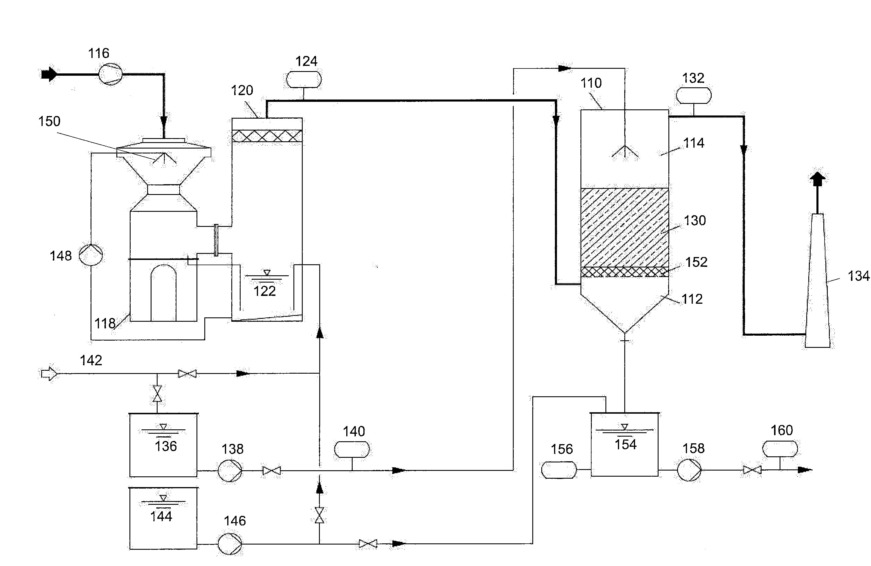
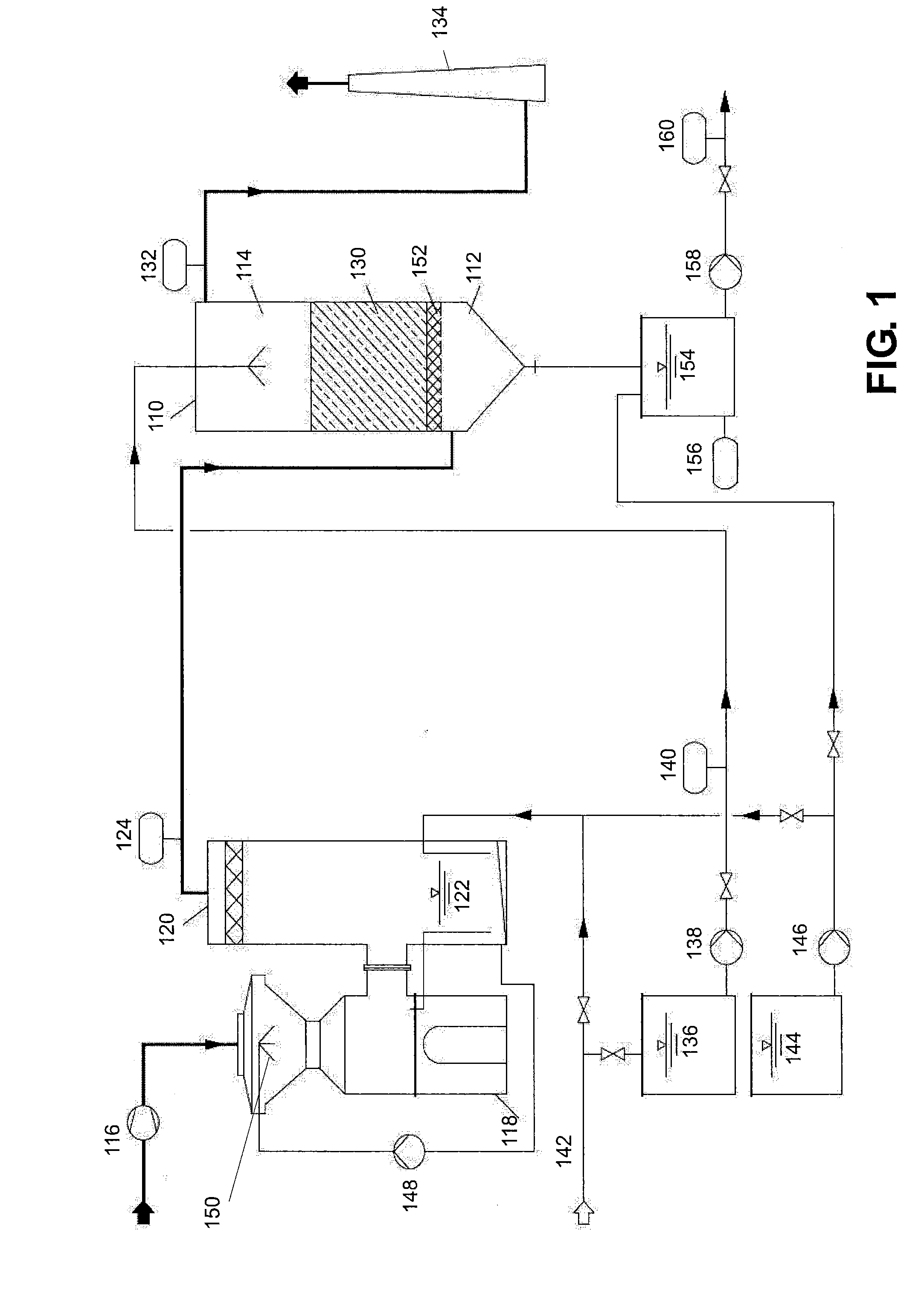
[0054]The test arrangement 1 shown in FIG. 1 in order to illustrate the invention comprises a test reactor 110, to the lower part 112 of which a test gas is supplied and into the upper part 114 of which water or a base is sprayed.

[0055]The test waste gas originates from natural gas combustion. The waste gas is dedusted with the assistance of an electrostatic dust filter (not shown) and passes via a fan 116 at approx. 300° C. into a venturi quencher 118. The holding tank 122, incorporated into the mist collector 120, of the venturi quencher 118 was filled with water or a 15% NaOH solution. The waste gases are cooled and saturated to saturation temperature in the venturi quencher 118.

[0056]A first measuring device 124 analyses the composition (NOx content, CO2 content, as well as O2 content and in some tests CxHy content), the temperature, the flow volume and the flow rate of the test waste gas.

[0057]The test gas then enters the reactor 110.

[0058]The reactor 11...


PUM

PropertyMeasurementUnit
Temperatureaaaaaaaaaa
Weightaaaaaaaaaa
Lengthaaaaaaaaaa

Abstract

The present invention relates to a method for the catalytic removal of carbon dioxide and NOx from waste gases in a reactor charged with activated carbon catalyst. The method comprises the following steps:
    • a. saturating the catalyst with water
    • b. saturating or partially saturating the waste gases with water,
    • c. introducing the waste gases into the reactor,
    • d. catalytically converting NOx into NO2 and, in parallel with this, catalytically converting CO2 into carbon and O2 on the same catalyst,
    • e. washing out the activated carbon catalyst with water and discharging the carbon as a solid and NO2— dissolved in water or in the base.

Description

TECHNICAL FIELD[0001]The present invention relates generally to a method for the catalytic removal of carbon dioxide and NOx from waste gases.PRIOR ART[0002]Discussions on climate change have clearly demonstrated to mankind that the resources available to us are limited and that the harmful substances produced by human activities have a major impact on the environment and lead to long-term climate change. After sulfur emissions took centre stage in the 1970s, carbon dioxide emissions have now become the key topic. Intensive research has been being carried out for some years now to find ways in which the production of this gas can be avoided where possible or else ways in which this gas can be removed from the atmosphere. With regard to the latter option various methods have been proposed for binding the carbon dioxide from the atmosphere to solids or liquids and then storing it. Such methods are known, for example, from WO2005108297A, KR2005028624 A and WO2004098740 A. It has also b...

Claims


Application Information

Patent Timeline
IPC IPC(8): B01D53/86
CPCB01D53/8628B01D53/8671B01J21/18B01D53/8646B01D2253/102B01D2255/702B01D2257/404B01D2257/504B01D2258/0283B01J37/10B01J38/48B01J38/64B01J35/0026B01J35/023B01J35/1023B01J37/0009Y02C20/40
Inventor STRICKROTH, ALAIN
Owner CPPE CARBON PROCESS & PLANT ENG
Why Eureka
Try Eureka