Multilayer inductor
a multi-layer inductor and inductor technology, applied in the direction of transformer/inductance details, inductance, basic electric elements, etc., can solve the problems of increasing the whole of the multi-layer inductor, increasing the cost of metal materials, and affecting etc., to achieve the effect of improving the conversion efficiency of converters, improving dc superposition characteristics, and easy saturation
- Summary
- Abstract
- Description
- Claims
- Application Information
AI Technical Summary
Benefits of technology
Problems solved by technology
Method used
Image
Examples
first embodiment
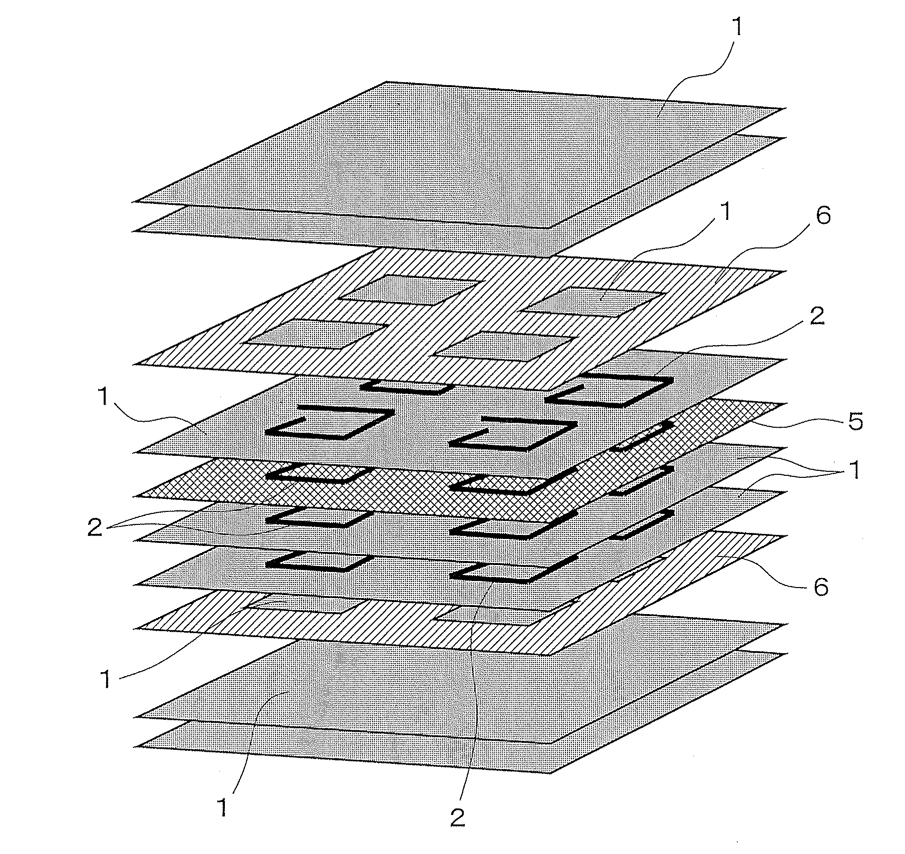
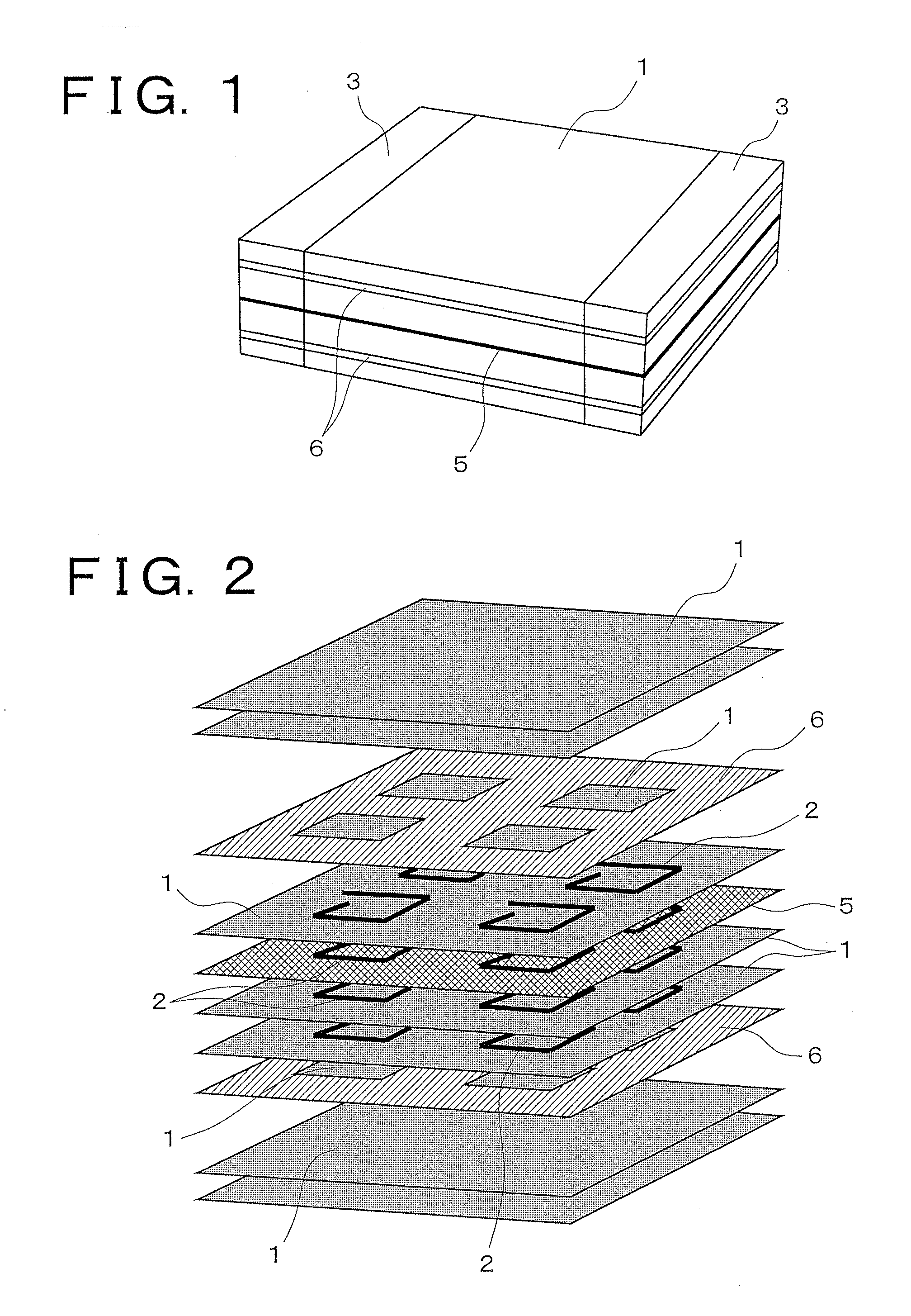
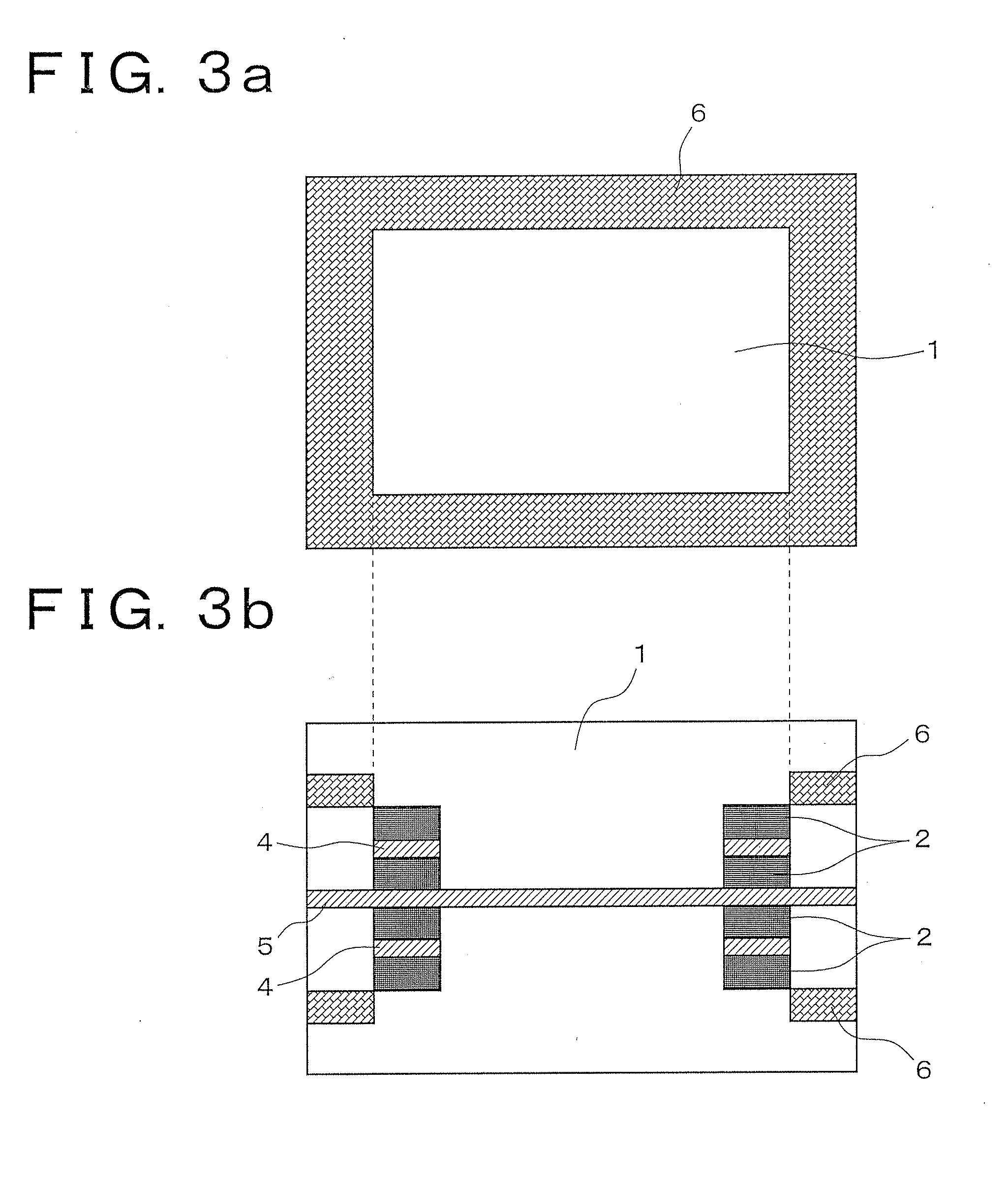
[0036]FIG. 1 to FIG. 3 each illustrate a first embodiment of a multilayer inductor according to the present invention, and FIG. 4 to FIG. 6 illustrate first to third modifications, respectively.
[0037]As illustrated in FIG. 1 to FIG. 3, this multilayer inductor is formed in a rectangular parallelepiped shape, in which a plurality of electrically insulating magnetic layers 1 and conductive patterns 2 are laminated, and each of the conductive patterns 2 is connected in sequence in a lamination direction, so that a spirally circulating coil 2 is formed inside a magnetic body configured by the magnetic layers 1, and both ends of the coil 2 are drawn out to be connected to external electrodes 3. The external electrodes 3 are connected to a land part of a circuit board (not shown), so that the multilayer inductor is surface-mounted.
[0038]Herein, between the conductive patterns 2 adjacent in the lamination direction, an electrically insulating nonmagnetic pattern 4 having a shape correspond...
second embodiment
[0050]FIG. 7 illustrates a second embodiment of a multilayer inductor according to the present invention, and FIG. 8 to FIG. 10 illustrate first to third modifications of the second embodiment, respectively. Hereinafter, the same components as the components illustrated in FIG. 1 to FIG. 6 are denoted by the same reference numerals, and the description thereof is simplified.
[0051]In each of these multilayer inductors, in axial view of a coil 2, a permanent magnet layer 6 magnetized so as to emit a magnetic flux whose direction is opposite to the direction of a magnetic flux excited by the coil 2 is disposed over the whole surface of the inside of the coil 2.
[0052]That is, in the multilayer inductor of the second embodiment, as illustrated in FIG. 7, an annular nonmagnetic pattern 7 made of a Zn ferrite material similar to the nonmagnetic pattern 4 formed between the conductive patterns 2 is formed at a layer above a conductive pattern 2 located at an uppermost layer in the figure in...
example
[0058]In order to verify the effects of the multilayer inductors according to the present invention, the DC superposition characteristics of the multilayer inductors of the present invention, and the DC superposition characteristics of multilayer inductors of comparative examples were obtained to be compared by simulation.
[0059]In both the multilayer inductors of the present invention and the multilayer inductors of the comparative examples, chip size was 2.5×2.0×1.0 mm, the number of turns of the internal conductor was 5 turns, a film thickness of the internal conductor was 120 μm, and the thickness of an insulating layer between the internal conductors was 15 μm.
[0060]First, FIG. 11 illustrates a case where the DC superposition characteristics of multilayer inductors (1) and (2) having the configurations shown in the first embodiment and the first modification are compared with the DC superposition characteristics of a multilayer inductor (3) of a comparative example formed with a...
PUM
| Property | Measurement | Unit |
|---|---|---|
| temperature | aaaaa | aaaaa |
| temperature | aaaaa | aaaaa |
| thickness | aaaaa | aaaaa |
Abstract
Description
Claims
Application Information
 - R&D
- Intellectual Property
- Life Sciences
- Materials
- Tech Scout
- Unparalleled Data Quality
- Higher Quality Content
- 60% Fewer Hallucinations
Browse by: Latest US Patents, China's latest patents, Technical Efficacy Thesaurus, Application Domain, Technology Topic, Popular Technical Reports.
© 2025 PatSnap. All rights reserved.Legal|Privacy policy|Modern Slavery Act Transparency Statement|Sitemap|About US| Contact US: help@patsnap.com


