Acoustic image generation apparatus and progress display method in generating an image using the apparatus

a technology of generating apparatus and generating image, which is applied in the field of generating image using acoustic image generator, can solve the problems of difficult for the user of the probe to understand the progress or the end point, and is difficult to understand until, so as to achieve the effect of easy confirmation of the progress of the scanning process

Active Publication Date: 2014-10-23
FUJIFILM CORP
View PDF4 Cites 9 Cited by
  • Summary
  • Abstract
  • Description
  • Claims
  • Application Information

AI Technical Summary

Benefits of technology

[0010]The present invention has been developed in view of the problem described above, and it is an object of the present invention to provide an acoustic image generation apparatus that facilitates, in generating an acoustic image by scanning a probe, confirmation of progress of the scanning process, and a display method of the progress.
[0028]Further, it is preferable that the acoustic image generation apparatus according to the present invention includes a control means that terminates the acoustic image generation process when a variation in the scanned length becomes greater than or equal to a predetermined value.
[0046]According to the acoustic image generation apparatus and the progress display method of the present invention, it is possible, in a scanning process in which a probe having an ultrasonic transducer is scanned in generating an acoustic image, to sequentially obtain a coordinate of the probe in real space, calculate a scanned length based on the sequentially obtained coordinate, and generate a progress level display that indicates progress of the scanning process based on the predetermined target scanning length and the scanned length. As a result, the user of the probe may visually confirm the progress, so that, in generating an acoustic image by scanning the probe, progress of the scanning process may be confirmed easily.

Problems solved by technology

In such a case, the conventional method has a problem that it is difficult for the user of the probe to understand the progress or the end point of the scanning process, i.e., it is difficult to understand until when (or to where) the probe needs to be scanned.

Method used


Image

  • Acoustic image generation apparatus and progress display method in generating an image using the apparatus
  • Acoustic image generation apparatus and progress display method in generating an image using the apparatus
  • Acoustic image generation apparatus and progress display method in generating an image using the apparatus

Examples


first embodiment

of Acoustic Image Generation Apparatus and Progress Display Method

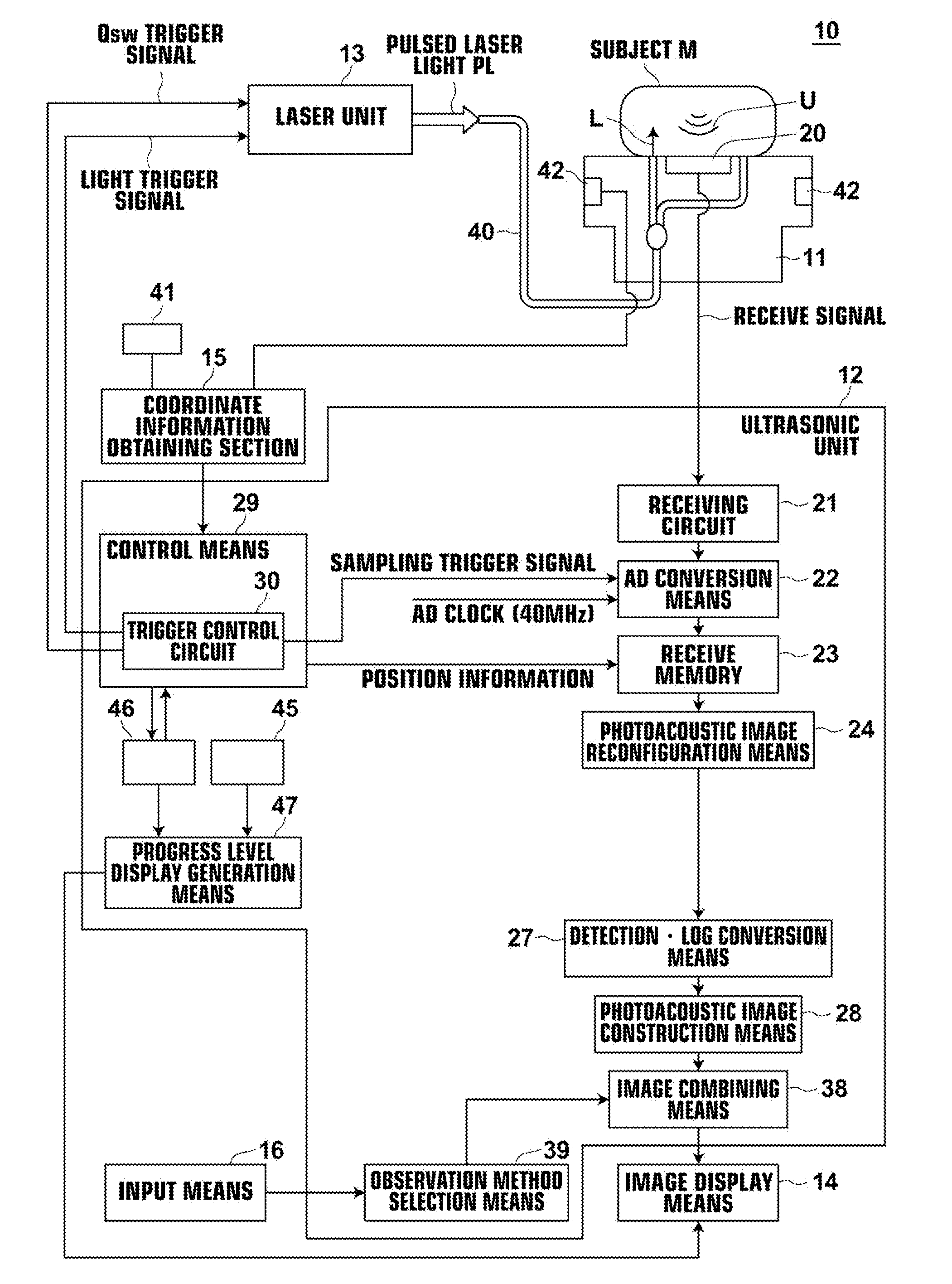
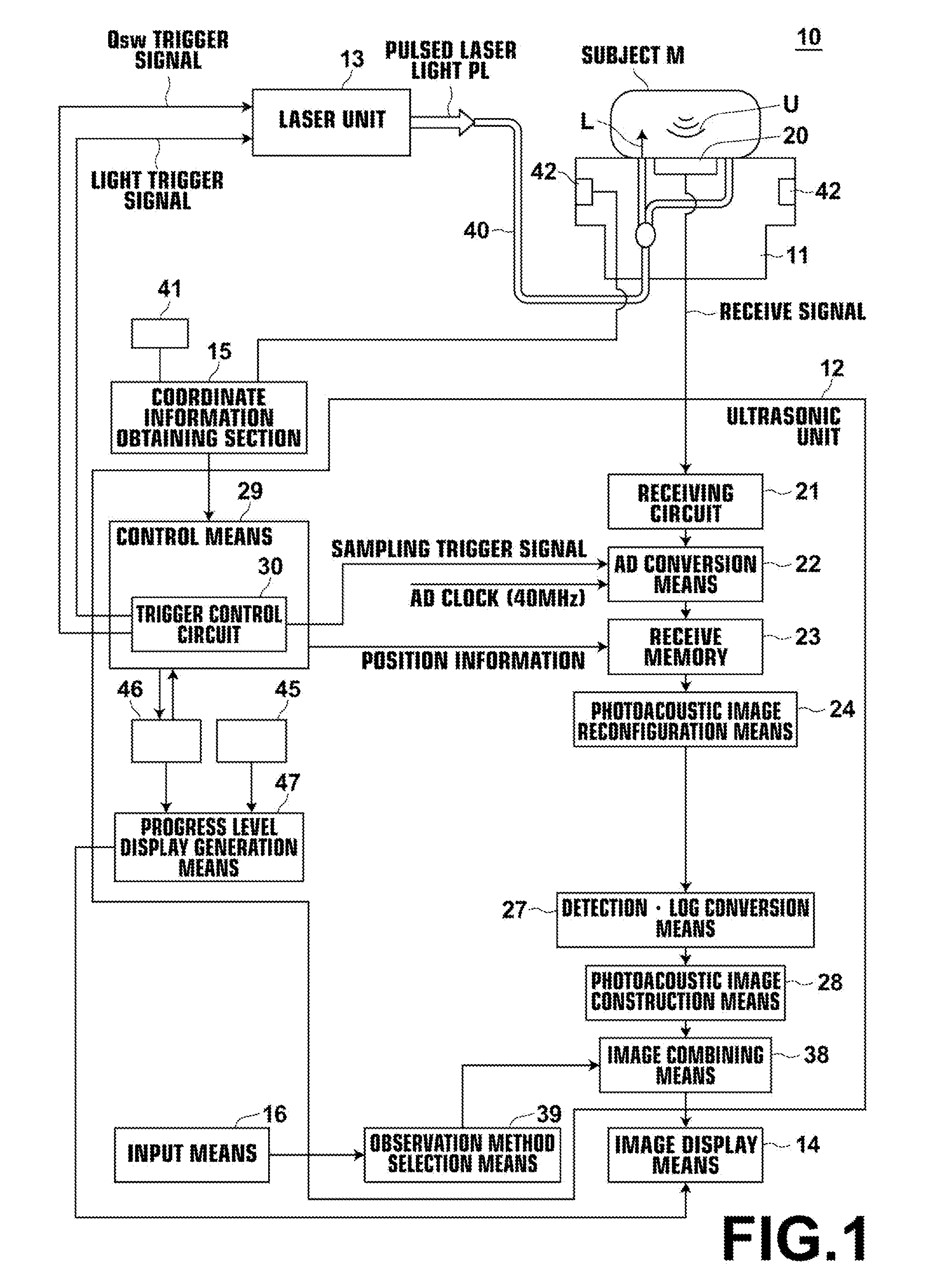
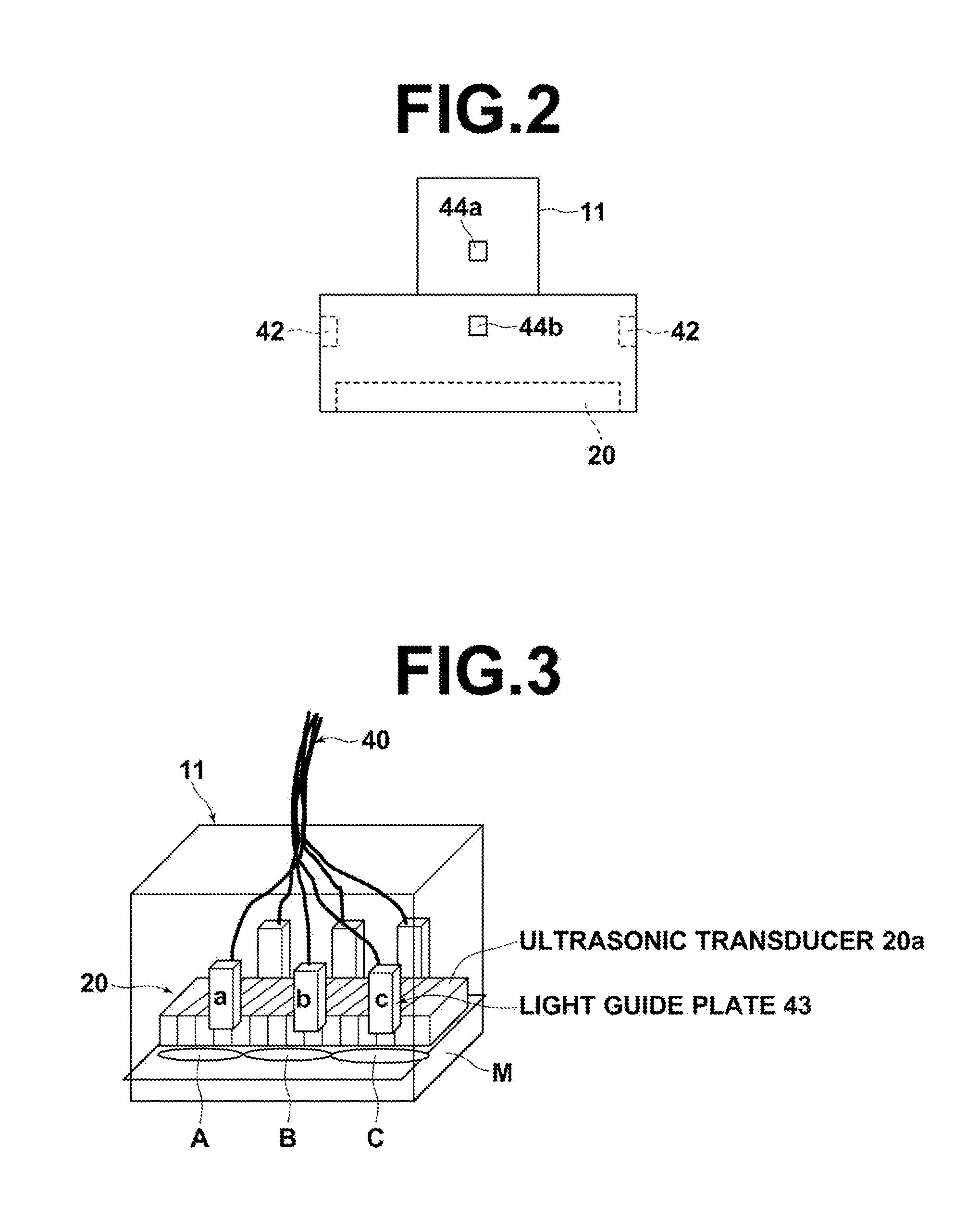
[0070]A first embodiment of the present invention will be described first in detail. In the following description, a photoacoustic image generation apparatus will be taken up as a specific example of acoustic image generation apparatus. FIG. 1 is a block diagram of the photoacoustic image generation apparatus of the present embodiment, illustrating the configuration thereof. FIG. 2 is a schematic external view of the probe and FIG. 3 is a schematic interval view of the probe.

[0071]The photoacoustic image generation apparatus 10 of the present embodiment includes an ultrasonic probe (probe) 11, an ultrasonic unit 12, a laser unit 13, an image display means 14, coordinate obtaining means 15, 41, and 42, and an input means 16.

[0072]The laser unit 13 outputs, for example, pulsed laser light PL as measuring light to be projected onto a subject M. The laser unit 13 is configured to output the pulsed laser light PL, for exam...

second embodiment

of Acoustic Image Generation Apparatus and Progress Display Method

[0127]A second embodiment of the present invention will be described next. FIG. 14 is a block diagram of a photoacoustic image generation apparatus according to the second embodiment, illustrating the configuration thereof. The present embodiment differs from the first embodiment in that it uses an acceleration sensor as the coordinate obtaining means. Therefore, the detailed description of the components identical to those of the first embodiment is omitted unless otherwise specifically required.

[0128]The photoacoustic image generation apparatus 10 of the present embodiment includes an ultrasonic probe (probe) 11, an ultrasonic unit 12, a laser unit 13, an image display means 14, a coordinate obtaining means 15 and 42a, and an input means 16.

[0129]In the present embodiment, the coordinate obtaining means is an acceleration sensor unit which is constituted by the coordinate information obtaining section 15 and the acc...

third embodiment

of Acoustic Image Generation Apparatus and Progress Display Method

[0132]Next, a third embodiment of the acoustic image generation apparatus and the progress display method of the present invention will be described in detail. FIG. 15 is a block diagram of an acoustic image generation apparatus according to the third embodiment, illustrating the configuration thereof. The present embodiment differs from the first embodiment in that it generates an ultrasonic image as a reflected acoustic wave image, in addition to a photoacoustic image. Therefore, the detailed description of the components identical to those of the first embodiment is omitted unless otherwise specifically required.

[0133]The photoacoustic image generation apparatus 10 of the present embodiment includes an ultrasonic probe (probe) 11, an ultrasonic unit 12, a laser unit 13, an image display means 14, a coordinate obtaining means 15, 41, and 42, and an input means 16, as in the first embodiment.

[0134]The ultrasonic unit...


PUM


Abstract

In an acoustic image generation apparatus with a probe having an ultrasonic transducer, providing a scanning length setting part that sets a target scanning length in a scanning process of the probe, a coordinate obtaining part that sequentially obtains a coordinate of the probe in real space, a scanned length calculation part that calculates a scanned length based on the coordinate obtained by the coordinate obtaining part, a progress level display generation part that generates a progress level display that indicates progress of the scanning process based on the target scanning length and the scanned length, and a display part that displays the progress level display.

Description

CROSS-REFERENCE TO RELATED APPLICATIONS[0001]This application is a Continuation of PCT International Application No. PCT / JP2012 / 008354 filed on Dec. 27, 2012 which claims priority under 35 U.S.C. §119 (a) to Japanese Patent Application No. 2011-287562 filed on Dec. 28, 2011 and Japanese Patent Application No. 2012-269400 filed on Dec. 10, 2012, the contents of which are hereby expressly incorporated herein by reference in its entirety.BACKGROUND OF THE INVENTION[0002]1. Technical Field[0003]The present invention relates to an acoustic image generation apparatus capable of generating tomographic images of ultrasonic images, photoacoustic images, and the like, and a progress display method in generating an image using the apparatus.[0004]2. Description of the Related Art[0005]Conventionally, ultrasonic imaging is known as a method for obtaining an internal tomographic image of a subject in which an ultrasonic image is generated by projecting an ultrasonic wave onto a subject and detec...

Claims


Application Information

Patent Timeline
Patent Type & Authority Applications(United States)
IPC IPC(8): A61B8/00A61B5/00
CPCA61B8/4245A61B5/0095A61B8/54A61B8/4254
Inventor IRISAWA, KAKUABE, TAKEYA
Owner FUJIFILM CORP
Why Eureka
Try Eureka