Industrial robot

a robot and industrial technology, applied in the direction of manipulators, joints, programmed manipulators, etc., to achieve the effect of reducing costs

Inactive Publication Date: 2014-10-30
SANKYO SEIKI MFG CO LTD
View PDF3 Cites 6 Cited by
  • Summary
  • Abstract
  • Description
  • Claims
  • Application Information

AI Technical Summary

Benefits of technology

[0008]In view of the problem described above, at least an embodiment of the present invention provides an industrial robot which is capable of reducing its cost while securing a relative positional accuracy of the movable part relative to the main body part.
[0011]Therefore, according to at least an embodiment of the present invention, a relative positional accuracy of the movable part relative to the main body part can be secured by using the first through the fourth rolling bearings which are a general-purpose component and whose accuracy such as dimensional accuracy is easily secured. In other words, according to at least an embodiment of the present invention, a cost of the industrial robot can be reduced while securing a relative positional accuracy of the movable part relative to the main body part. Further, in at least an embodiment of the present invention, a tension coil spring is not required to dispose in the second joint part and the third joint part like the industrial robot described in Patent Literature 1 and thus the weights of the second joint part and the third joint part can be reduced. Further, in the industrial robot described in Patent Literature 1, the recessed part of a joint socket and a ball are contacted with each other and thus wears of the joint socket and the ball lead to a problem. However, according to at least an embodiment of the present invention, the first through the fourth rolling bearings are used and thus this problem does not occur.
[0013]In at least an embodiment of the present invention, it is preferable that the second joint part includes a first urging member which urges the inner ring or the outer ring of the first rolling bearing toward one side in the first direction to prevent rattling between the inner ring and the outer ring of the first rolling bearing, and a second urging member which urges the inner ring or the outer ring of the second rolling bearing toward one side in the second direction to prevent rattling between the inner ring and the outer ring of the second rolling bearing. According to this structure, rattling between the inner ring and the outer ring of the first rolling bearing, and rattling between the inner ring and the outer ring of the second rolling bearing are prevented to enhance relative positional accuracy of the movable part relative to the main body part.
[0016]In at least an embodiment of the present invention, it is preferable that the third joint part includes a third urging member which urges the inner ring or the outer ring of the third rolling bearing toward one side in the first direction to prevent rattling between the inner ring and the outer ring of the third rolling bearing, and a fourth urging member which urges the inner ring or the outer ring of the fourth rolling bearing toward one side in the second direction to prevent rattling between the inner ring and the outer ring of the fourth rolling bearing. According to this structure, rattling between the inner ring and the outer ring of the third rolling bearing, and rattling between the inner ring and the outer ring of the fourth rolling bearing are prevented to enhance relative positional accuracy of the movable part relative to the main body part.
[0018]In at least an embodiment of the present invention, it is preferable that the first rolling bearing, the second rolling bearing, the third rolling bearing and the fourth rolling bearing are a ball bearing. The ball bearing is capable of receiving a load in a radial direction and a load in a thrust direction and thus, according to this structure, two kinds of a bearing, i.e., a radial bearing and a thrust bearing are not required to be used as the first rolling bearing, the second rolling bearing, the third rolling bearing and the fourth rolling bearing. Therefore, the structures of the second joint part and the third joint part are simplified and the sizes and the weights of the second joint part and the third joint part can be reduced. Further, a cost of the industrial robot can be further reduced.
[0020]As described above, in the industrial robot in accordance with at least an embodiment of the present invention, its cost can be reduced while securing relative positional accuracy of the movable part relative to the main body part.

Problems solved by technology

Further, in the industrial robot described in Patent Literature 1, the recessed part of a joint socket and a ball are contacted with each other and thus wears of the joint socket and the ball lead to a problem.

Method used


Image

  • Industrial robot
  • Industrial robot
  • Industrial robot

Examples


Embodiment Construction

[0032]An embodiment of the present invention will be described below with reference to the accompanying drawings.

(Schematic Structure of Industrial Robot)

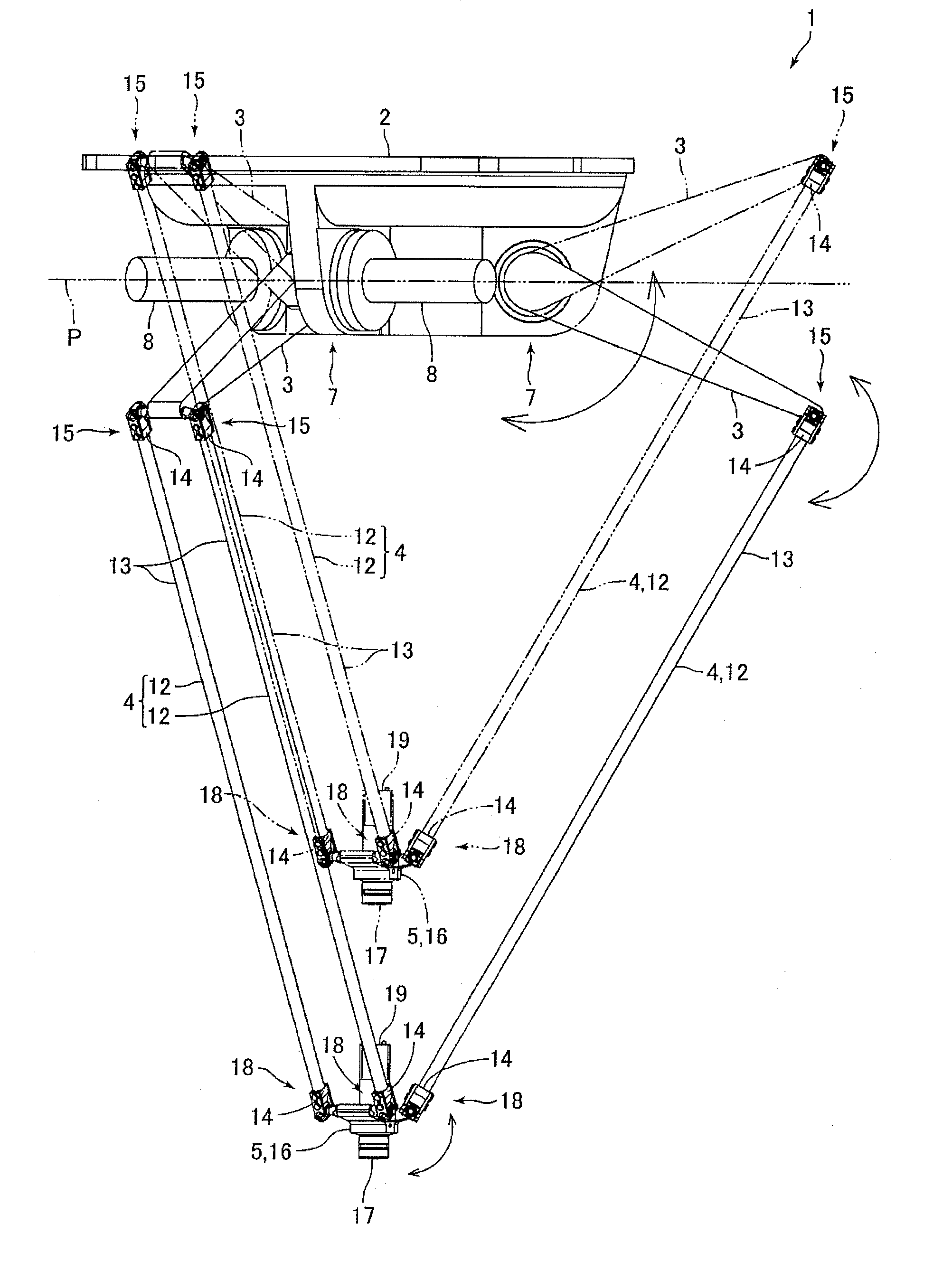
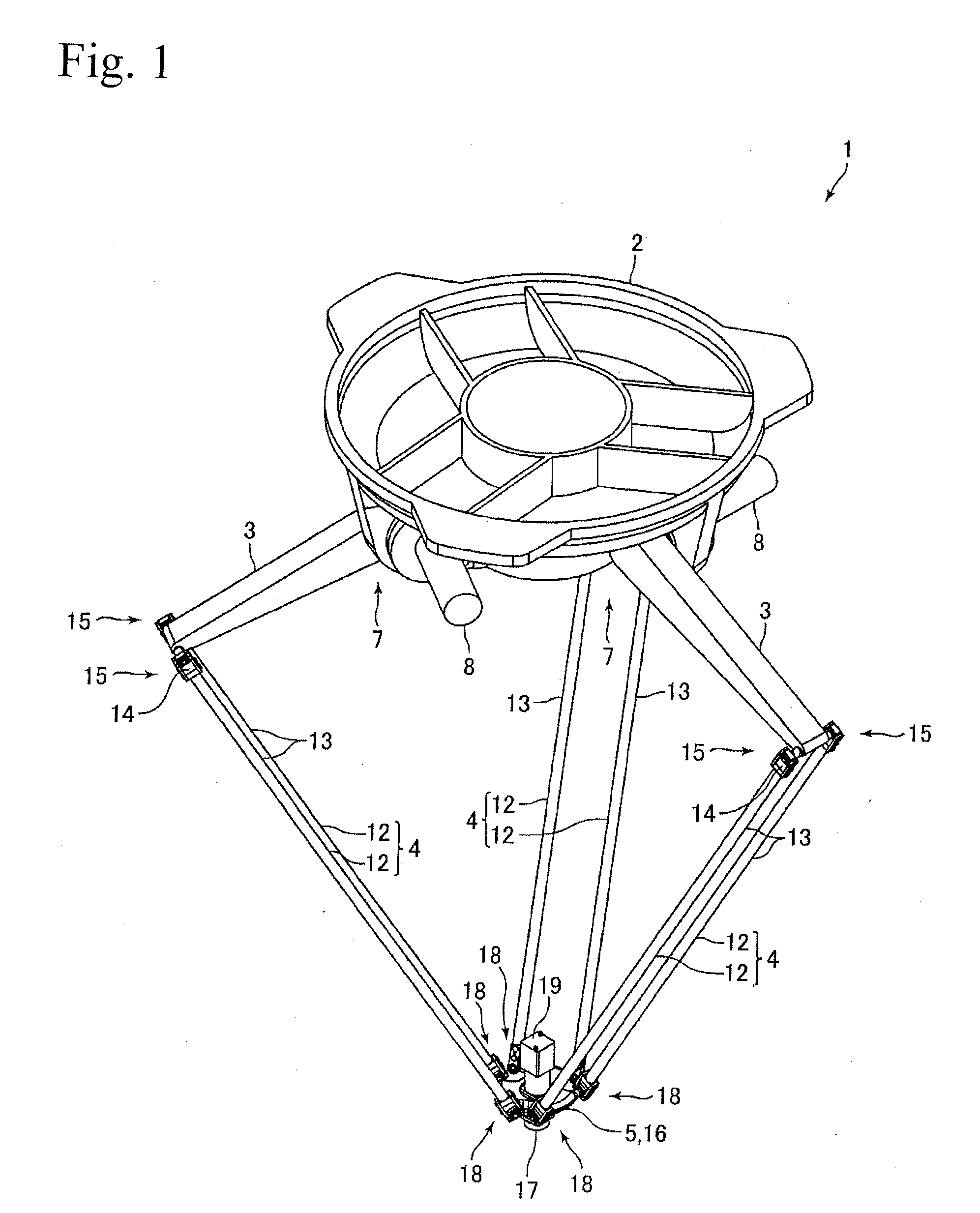
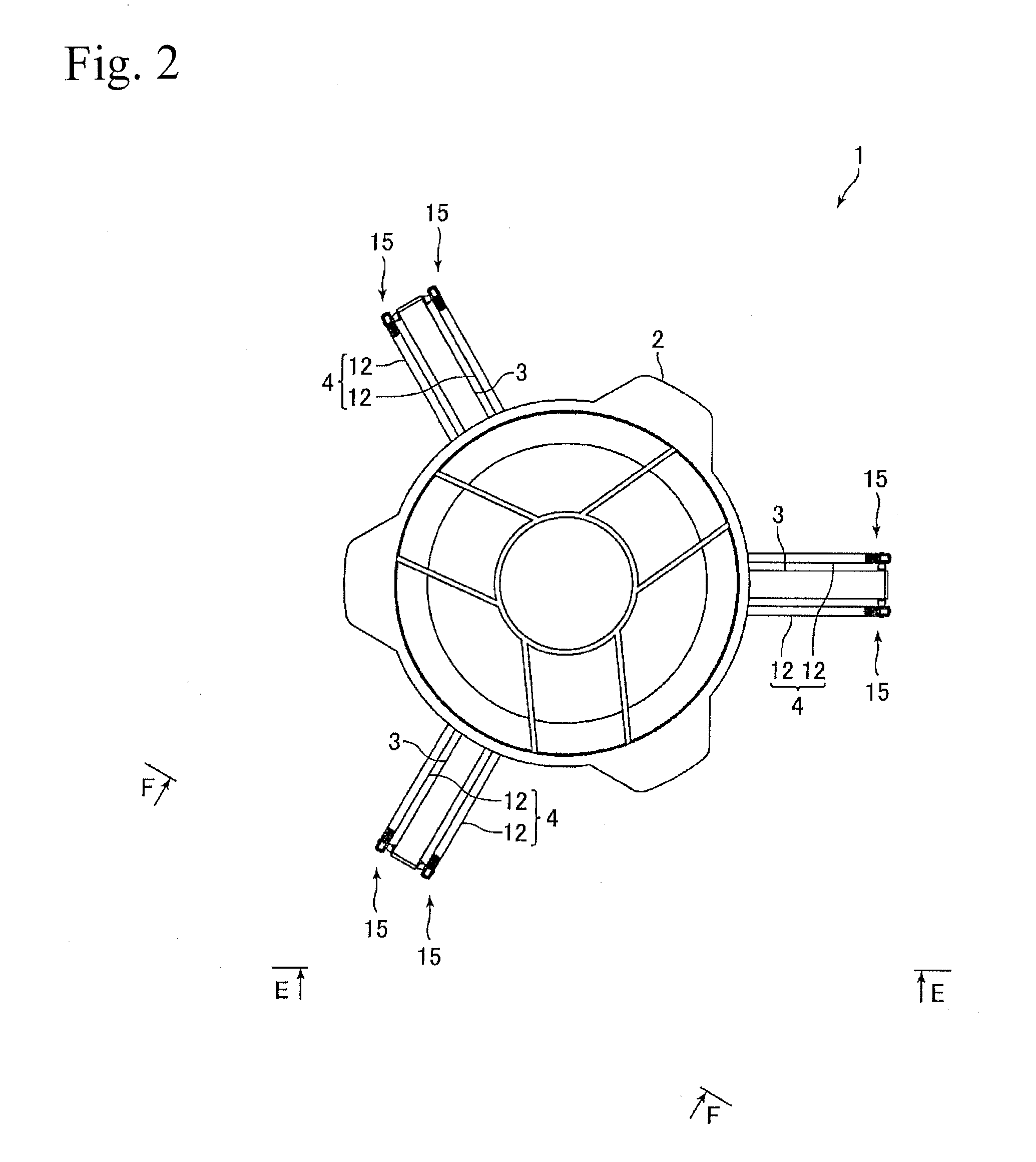
[0033]FIG. 1 is a perspective view showing an industrial robot 1 in accordance with an embodiment of the present invention. FIG. 2 is a plan view showing the industrial robot 1 in FIG. 1. FIG. 3 is a side view showing the industrial robot 1 which is viewed in the “E-E” direction in FIG. 2. FIG. 4 is a side view showing the industrial robot 1 which is viewed in the “F-F” direction in FIG. 2. FIG. 5 is a bottom view showing the industrial robot 1 in FIG. 1. FIG. 6 is a plan view for explaining a part of the industrial robot 1 shown in FIG. 1.

[0034]An industrial robot 1 in this embodiment is a so-called parallel link type industrial robot. Further, the industrial robot 1 in this embodiment is, for example, a robot for conveying a work such as an electronic component. The industrial robot 1 includes a main body part 2, three levers 3 c...


PUM


Abstract

An industrial robot may include a main body part; a plurality of levers having base end sides turnably connected with the main body part; a plurality of arm parts having respective base end sides turnably connected with respective tip end sides of the plurality of the levers; a movable part which is turnably connected with the respective tip end sides of the plurality of the arm parts; and a plurality of turning drive mechanisms for respectively turning the plurality of the levers. The plurality of the levers may radially extend to an outer peripheral side of the main body part at a substantially equal pitch. The arm part may provided with two arms which are mutually parallel to each other and are formed in a straight shape;

Description

CROSS REFERENCE TO RELATED APPLICATIONS [0001]This is the U.S. national stage of application No. PCT / JP2012 / 082278, filed on Dec. 13, 2012. Priority under 35 U.S.C. §119(a) and 35 U.S.C. §365(b) is claimed from Japanese Application No. 2012-001380, filed Jan. 6, 2012, the disclosure of which is also incorporated herein by reference.FIELD OF THE INVENTION [0002]The present invention relates to a so-called parallel link type industrial robot.BACKGROUND [0003]Conventionally, a so-called parallel link type industrial robot has been known as an industrial robot for conveying a work such as an electronic component (see, for example, Patent Literature 1). The industrial robot described in Patent Literature 1 includes a main body part, three levers which are turnably connected with the main body part, three sets of parallel links which are respectively connected with three levers, and a movable part connected with three sets of the parallel links. The three levers are connected with the mai...

Claims


Application Information

Patent Timeline
Patent Type & Authority Applications(United States)
IPC IPC(8): B25J9/00B25J17/02
CPCB25J17/0216B25J9/0051Y10T74/20329B25J11/00B25J17/00B25J17/0258B25J17/0266
Inventor YAZAWA, TAKAYUKIYOSHIZAWA, YUTAKAFUJIWARA, MASASHI
Owner SANKYO SEIKI MFG CO LTD
Why Eureka
Try Eureka