Thread whirling device and turning machine comprising a thread whirling device

a technology of whirling device and turning machine, which is applied in the direction of auxilary equipment, manufacturing tools, total factory control, etc., can solve the problems of long manual adjustment, complex and disadvantageous translation mechanism, and the inability of the thread whirling head to be received on the spindle of the turning machine, etc., to achieve high time efficiency, efficient and simple manner, and simple

Active Publication Date: 2014-10-30
GILDEMEISTER ITALANA
View PDF5 Cites 8 Cited by
  • Summary
  • Abstract
  • Description
  • Claims
  • Application Information

AI Technical Summary

Benefits of technology

The invention is about a thread whirling device for a turning machine. It includes two separate drive means- one for high-speed cutting and another for adjusting the angle of the whirling head. This means that any manual adjustments to the head's angle can be made automatically, which saves time and makes the process less complex. The device is designed to make medical whirlings more efficiently and accurately, especially when processing different workpieces.

Problems solved by technology

In order to even enable the required precision in this adjustment of the inclination angle by means of manual adjustment, it is necessary to provide complex and disadvantageously large translation mechanisms which can translate manual adjustment movements into minimal adjustment movements.
In most cases, screws for medical technology are not mass-produced articles, but instead individually produced workpieces so that in practice, often before the processing of each individual workpiece, such a lengthy manual adjustment is required.
In this instance, however, there Is also the disadvantage that a spindle or a spindle drive of the processing centre has to be used to drive the thread whirling head and axes of the processing centre have to be used to control the thread whirling head since the thread whirling head has no separate drive means at all.
In addition, such a thread whirling head is not suitable for use on a turning machine having a workpiece-carrying spindle since the spindle of a turning machine is configured to receive the workpiece (workpiece-carrying spindle in contrast to a workpiece-carrying spindle of a milling machine or a processing centre), and the thread whirling head consequently cannot be received on the spindle of the turning machine and consequently cannot be driven by means of the spindle.

Method used


Image

  • Thread whirling device and turning machine comprising a thread whirling device
  • Thread whirling device and turning machine comprising a thread whirling device
  • Thread whirling device and turning machine comprising a thread whirling device

Examples


Embodiment Construction

[0046]Preferred embodiments of the present invention are described in detail below with reference to the appended figures. However, the present invention is not limited to the embodiments described. The present invention is defined by the scope of the claims. Features of the embodiments which are the same or similar are given the same reference numerals in the figures.

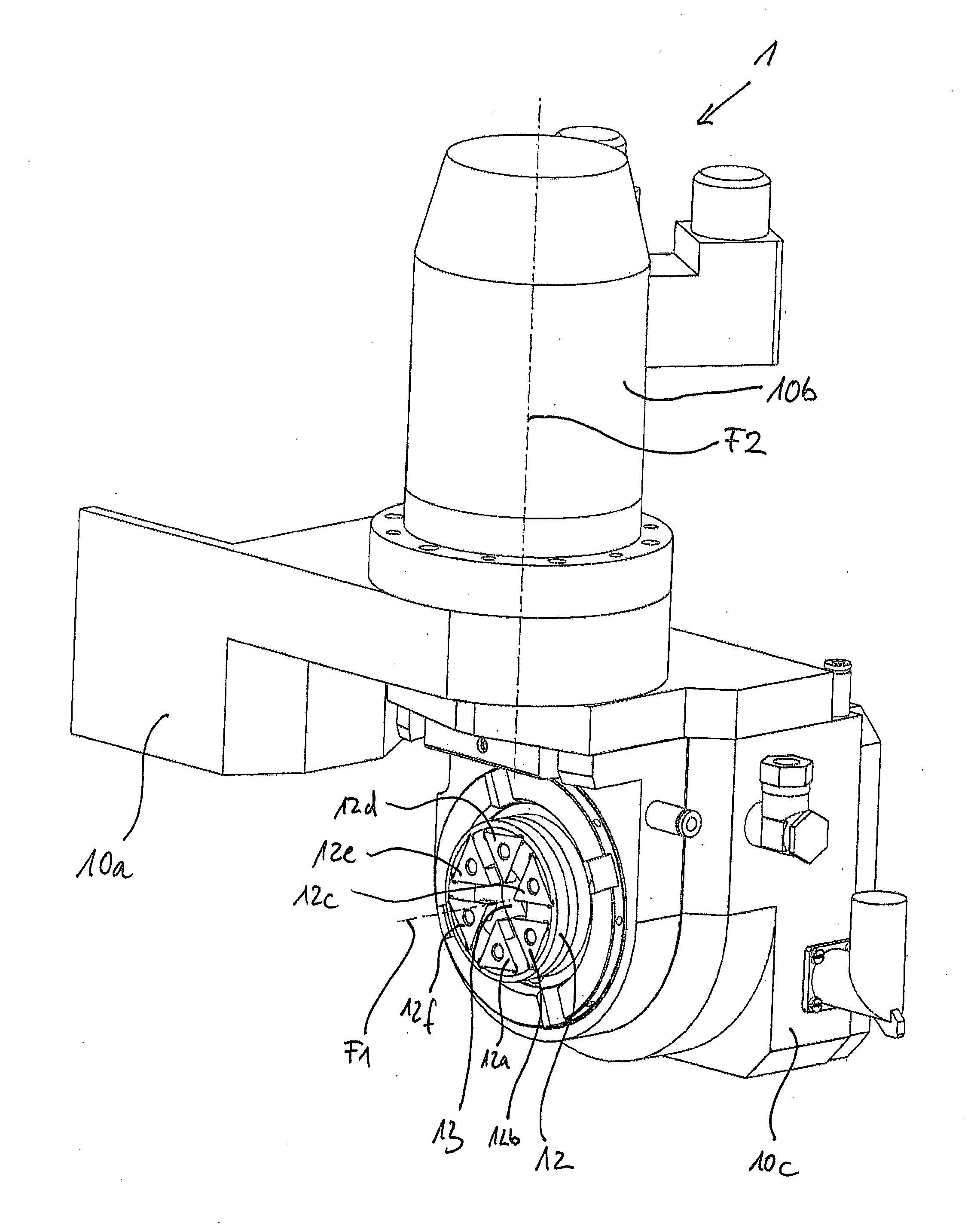
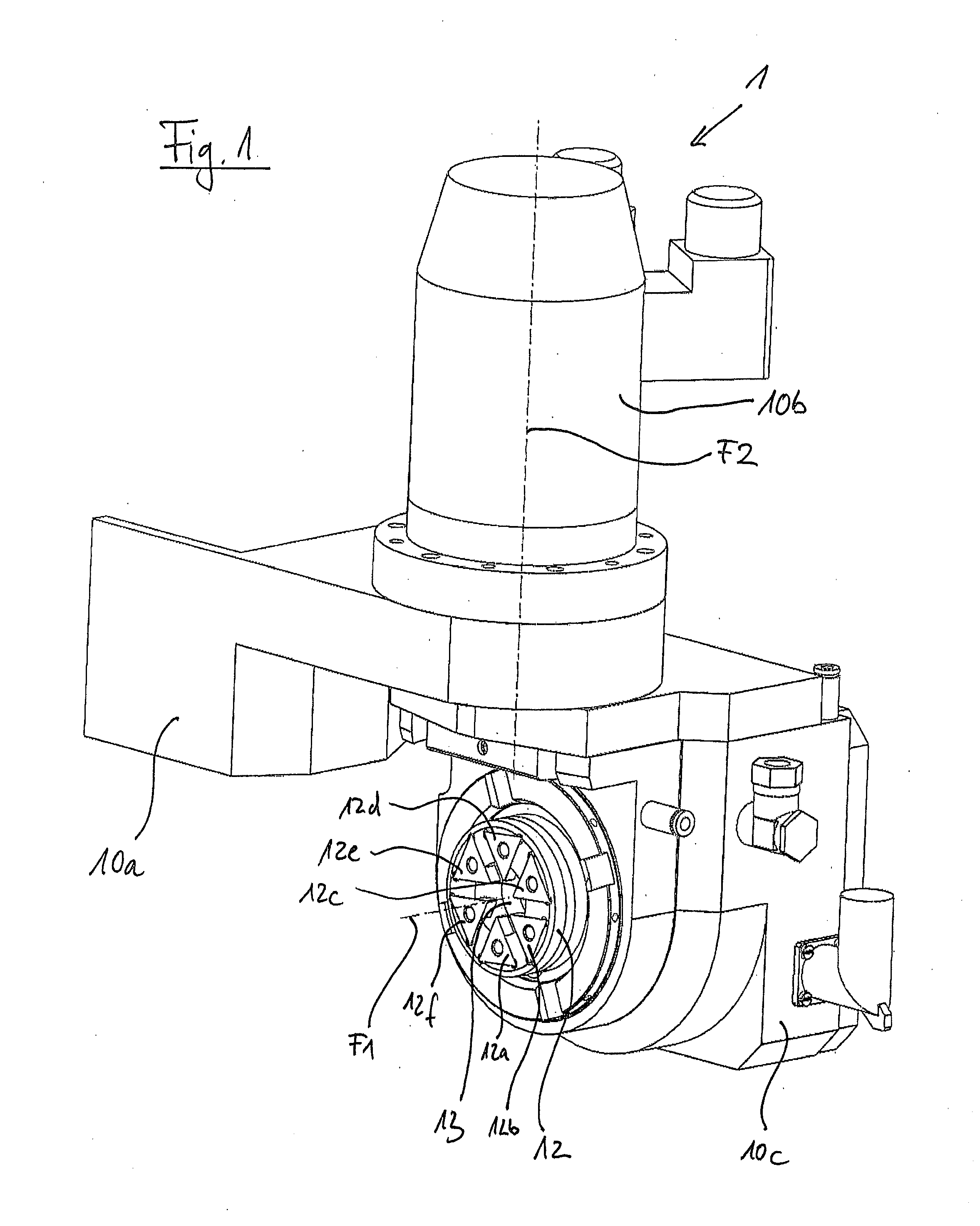
[0047]FIG. 1 is an exemplary schematic, perspective view of a thread whirling device 1 according to a preferred embodiment of the present invention. The thread whirling device 1 can be fitted to a turning machine by means of a retention portion 10a of a retention structure of the thread whirling device 1, which structure further comprises a drive housing portion 10b and a whirling head retention portion 10c. There is retained on the whirling head retention portion 10c a whirling head 12 which is rotatably supported about a rotation axis F1 and which for thread whirling is driven at high speeds about the rotation axis F...


PUM

PropertyMeasurementUnit
Angleaaaaaaaaaa
Angleaaaaaaaaaa
Angleaaaaaaaaaa

Abstract

A thread whirling device for producing a thread on a workpiece on a numerically controlled turning machine by a thread whirling method, having a retention structure for fitting the thread whirling device to the turning machine, a whirling head which is retained on the retention structure, has an opening and carries one or more cutters which are arranged peripherally on the edge of the opening, having a first drive device which is configured to drive the whirling head in a rotational manner about a first rotation axis which extends through the opening. The thread whirling device further includes a second drive device which is configured to drive the whirling head in a rotational manner about a second rotation axis which extends transversely relative to the first rotation axis, in order to orientate an angle between the first rotation axis and the spindle axis of the turning machine work spindle.

Description

[0001]The present invention relates to a thread whirling device for producing a thread on a workpiece on a numerically controlled turning machine by means of a thread whirling method, having a retention structure for fitting the thread whirling device to the turning machine, having a whirling head which is retained on the retention structure and which has an opening and which carries one or more cutters which are arranged peripherally on the edge of the opening, and having a first drive means which is configured to drive the whirling head in a rotational manner about a first rotation axis which extends through the opening. In addition, the present invention relates to a numerically controlled turning machine having an work spindle for receiving a workpiece and for rotationally driving the workpiece about a spindle axis of the work spindle and a thread whirling device.BACKGROUND OF THE INVENTION[0002]A generic thread whirling device according to the preamble of claim 1 is known from ...

Claims


Application Information

Patent Timeline
IPC IPC(8): B23G1/34B23B5/46
CPCB23G1/34B23B5/46B23B2220/52B23G2240/40B23B2215/68B23G2240/60B23B11/00B23B25/00B23G3/00Y10T82/2527Y10T82/2502Y02P90/02
Inventor RIGOLONE, FRANCOROTA, RENATOCAVADINI, MARCOMILESI, LUCA
Owner GILDEMEISTER ITALANA
Why Eureka
Try Eureka