

Tag assembly
- Summary
- Abstract
- Description
- Claims
- Application Information
AI Technical Summary
Benefits of technology
Problems solved by technology
Method used
Image

Examples
Embodiment Construction
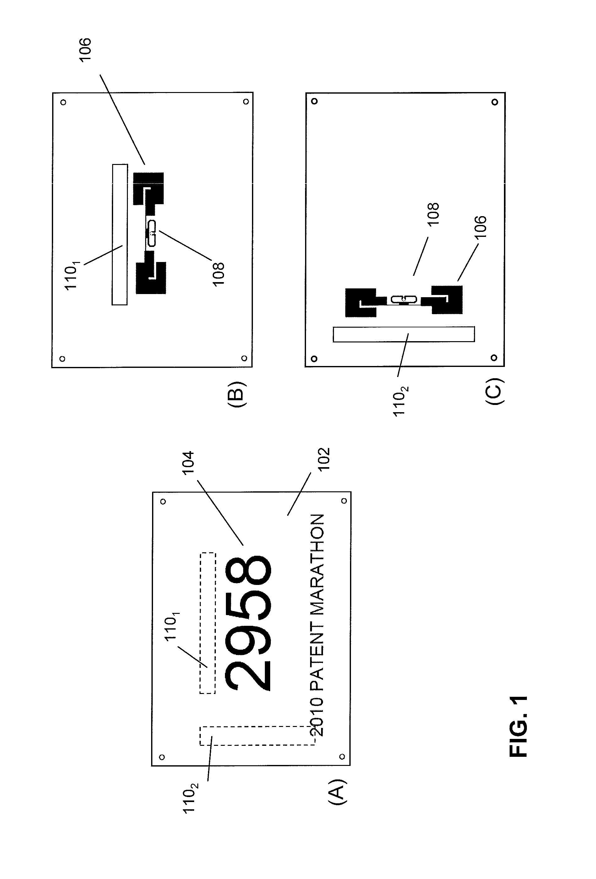
[0036]FIG. 1A-1C schematically depict bib tag assemblies according to various embodiment of the invention. In particular, FIGS. 1A and 1B depict the front and backside of a bib tag assembly for use e.g. in a sports event comprising a support sheet 102, e.g. a flexible, light-weight, water-resistant, sheet-like material that is adapted to be affixed to a person through the use of an adhesive or mechanism to pin or tie the support sheet to the person or animal (or clothing on the person or animal). Exemplary materials used for support sheet include fabric, paper, woven sheet, plastic or any combination thereof. Preferably, a front side of the support sheet may display an identifier such as an identifier 104 identifying the person to which the support sheet is affixed. Support sheet 102 may have a rectangular, 4-sided shape, but in other embodiment it may have any suitable shape, e.g., shape of a logo.
[0037]FIG. 1B depicts the backside of the support sheet to which at least one tag 108...
PUM
 Abstract
Description
Claims
Application Information