
Device for assembling capacitors for an electronic converter

a technology of capacitors and electronic converters, which is applied in the association of printed circuit non-printed electric components, laminated bus-bars, transportation and packaging, etc., can solve the problems of disrupting the functioning of the electric circuit, difficult to use electronic converters, etc., and achieve the effect of reducing the inductance of the current conductor system

Active Publication Date: 2014-10-30
VALEO EQUIP ELECTRIC MOTEUR
View PDF0 Cites 27 Cited by
  • Summary
  • Abstract
  • Description
  • Claims
  • Application Information

AI Technical Summary

Benefits of technology

The invention is a device that allows for the assembly of capacitors in a motor vehicle using bus bars that are independent from the electric circuit of the converter. This is useful for applications that require a strong current and reduces the inductance of the current conductor systems by arranging the bus bars.

Problems solved by technology

The technical problem addressed in this patent text is the difficulty of using electronic converters in applications that require strong currents and the potential disruption caused by strong inductance.

Method used


Image

  • Device for assembling capacitors for an electronic converter
  • Device for assembling capacitors for an electronic converter
  • Device for assembling capacitors for an electronic converter

Examples


first embodiment

[0101]FIG. 5a illustrates the assembly of the parts of the device for assembling fitted with the capacitors 200 according to the device 100 for assembling without a support part 13.

second embodiment

[0102]FIG. 5b illustrates the assembly of the parts of the device for assembling fitted with the capacitors 200 according to the device 100 for assembling with a support part 13.

[0103]As previously described, the device 100 for assembling makes it possible to assemble capacitors 200 for an electronic converter 300. As illustrated in FIG. 6, the device 100 for assembling is arranged in a vessel 500 which comprises:[0104]receptacles 501 to receive the assembled capacitors 200. These receptacles have a cylindrical form in order to receive the cylindrical capacitors, and have a diameter which is substantially larger than the diameter of the capacitors, such as to have play;[0105]an indexing orifice 503 corresponding to the indexing part 133 into which the said part 133 will be inserted;[0106]a securing orifice 502 corresponding to the securing orifice 132 of the support part 13 into which a screw can be introduced.

[0107]It will be noted that the indexing part 133 makes it possible to en...


PUM

PropertyMeasurementUnit
Polarityaaaaaaaaaa
Widthaaaaaaaaaa

Abstract

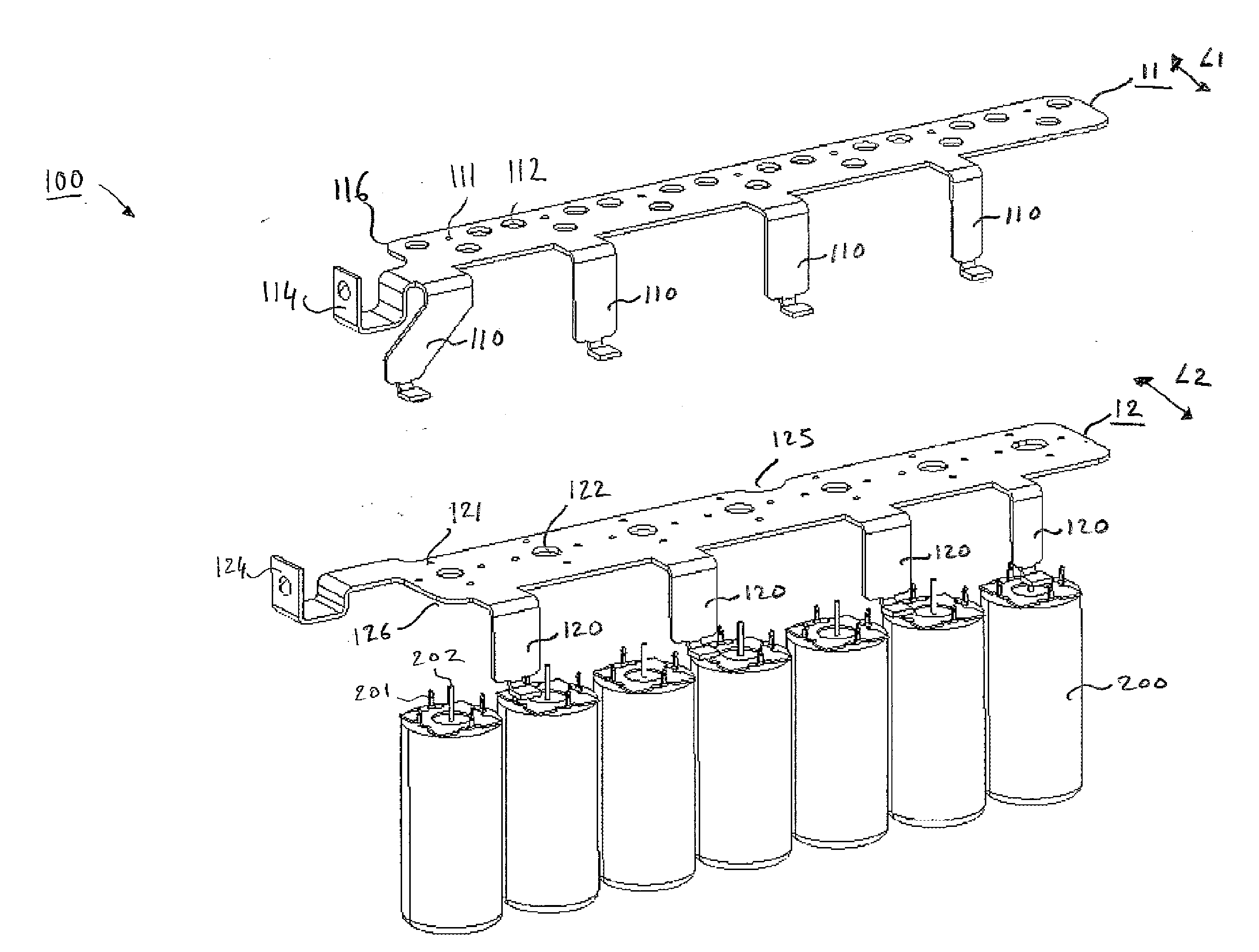
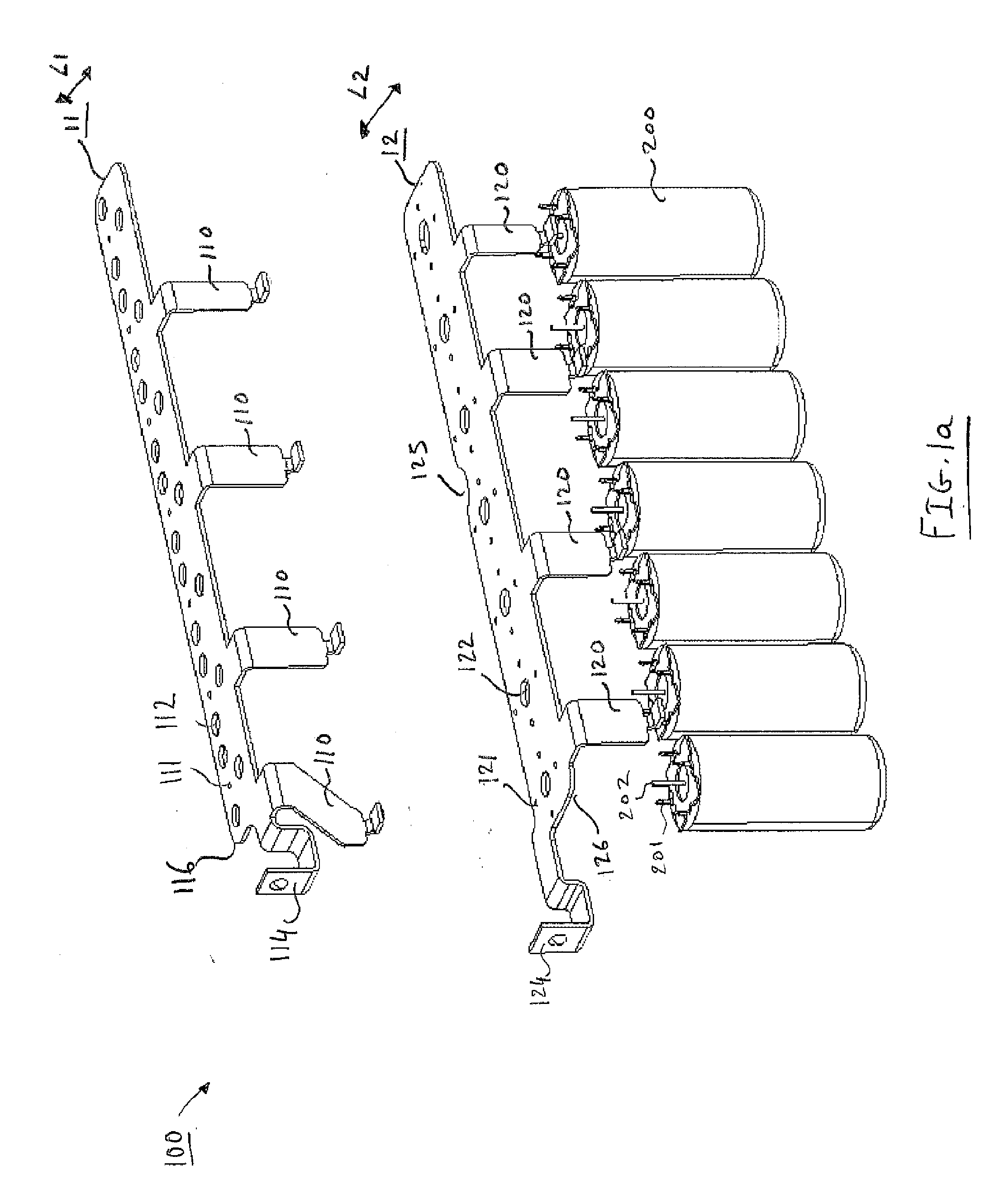
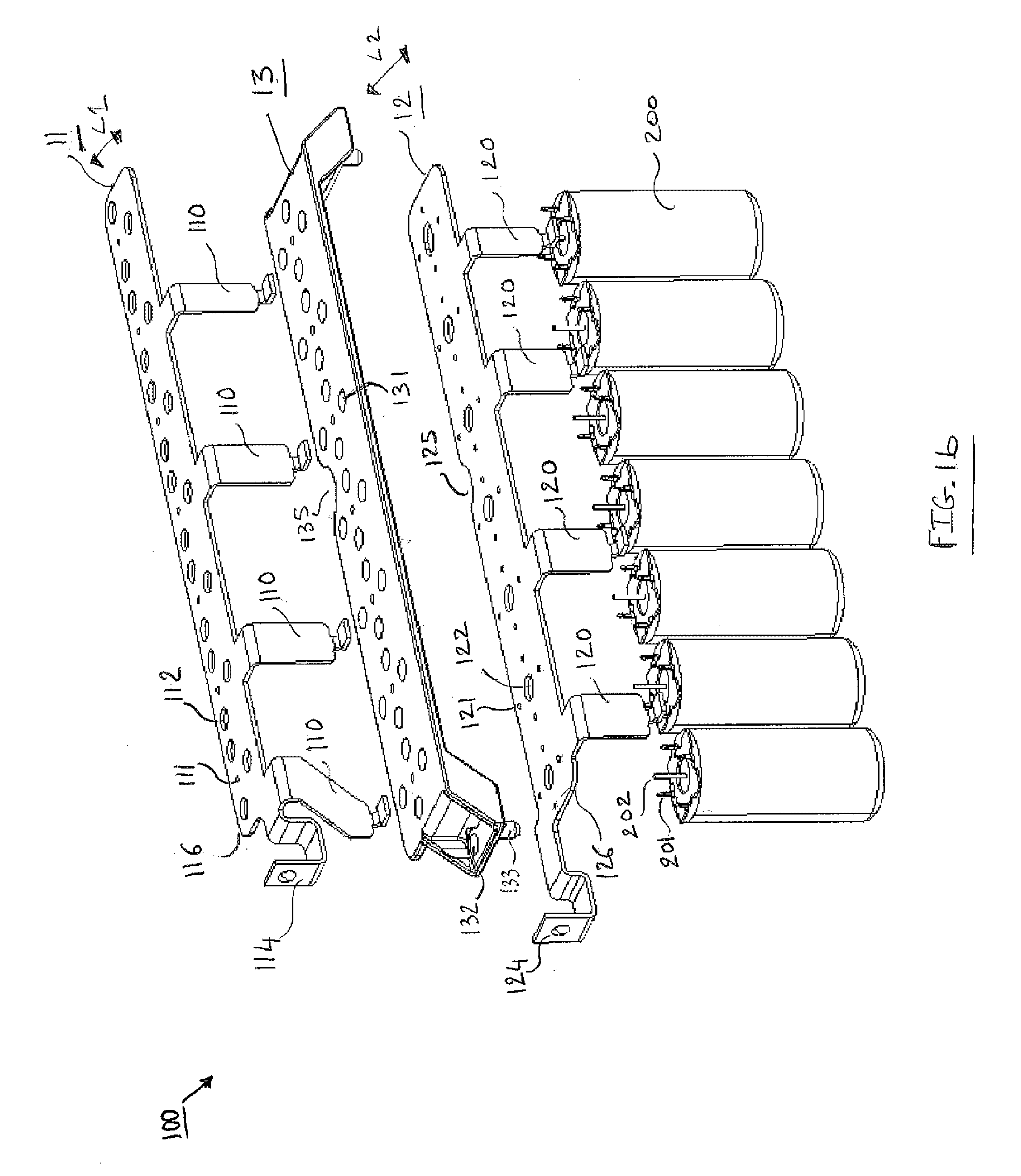
The device (100) for assembling capacitors (200) is intended for an electronic converter with a plurality of arms provided with transistors. The device comprises a bus bar (11) with positive polarity and a bus bar (12) with negative polarity. The bus bar with positive polarity and the bus bar with negative polarity are superposed one on top of the other without electrical contact. Preferably, the bus bar with positive polarity comprises a width (L1) smaller than the width (L2) of the bus bar with negative polarity. The device further comprises a support part (13) for insulating and indexing, arranged between the bus bar with positive polarity and the bus bar with negative polarity. The support part for insulating and indexing is typically formed from PBT plastic material reinforced with fibreglass.

Description


Claims


Application Information

Patent Timeline
Owner VALEO EQUIP ELECTRIC MOTEUR
Learn More