Back light unit with light guide plate preventing dark area between leds

a backlight unit and light guide technology, which is applied in the direction of planar/plate-like light guides, lighting and heating apparatuses, instruments, etc., can solve the problems of increased cost, non-uniform brightness, and formed dark area between leds, so as to reduce the number of leds and achieve uniform brightness , the effect of low cos

Inactive Publication Date: 2014-10-30
HB TECH CO LTD
View PDF6 Cites 1 Cited by
  • Summary
  • Abstract
  • Description
  • Claims
  • Application Information

AI Technical Summary

Benefits of technology

[0013]The intent of the present invention, for the purpose of solving the drawbacks aforementioned, is to compensate the brightness in the gap between LEDs, which may be a dark area, even under the condition that the gap between the LE

Problems solved by technology

However, because most of the light irradiated from the LED may proceed frontward and thus, a relatively small amount of the light may proceed laterally, the light irradiated from the LED may be non-uniformly provided to the light incidence plane of the light guide plate and accordingly, a dark area may be formed between the LEDs and non-uniform brightness may ensue.
Thus, it may be required to dispose the LEDs at a narrower interval to prevent an occurrence of the da

Method used


Image

  • Back light unit with light guide plate preventing dark area between leds
  • Back light unit with light guide plate preventing dark area between leds
  • Back light unit with light guide plate preventing dark area between leds

Examples


embodiment 1

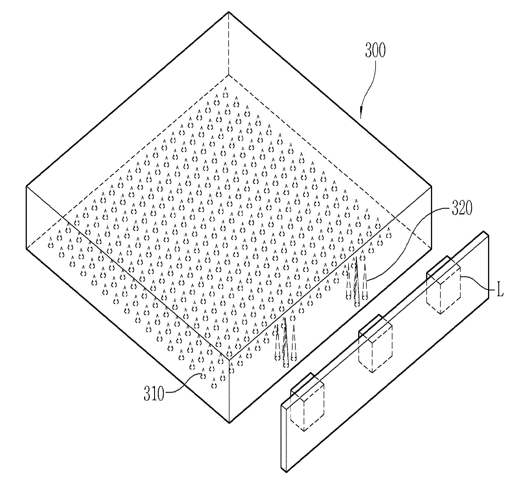
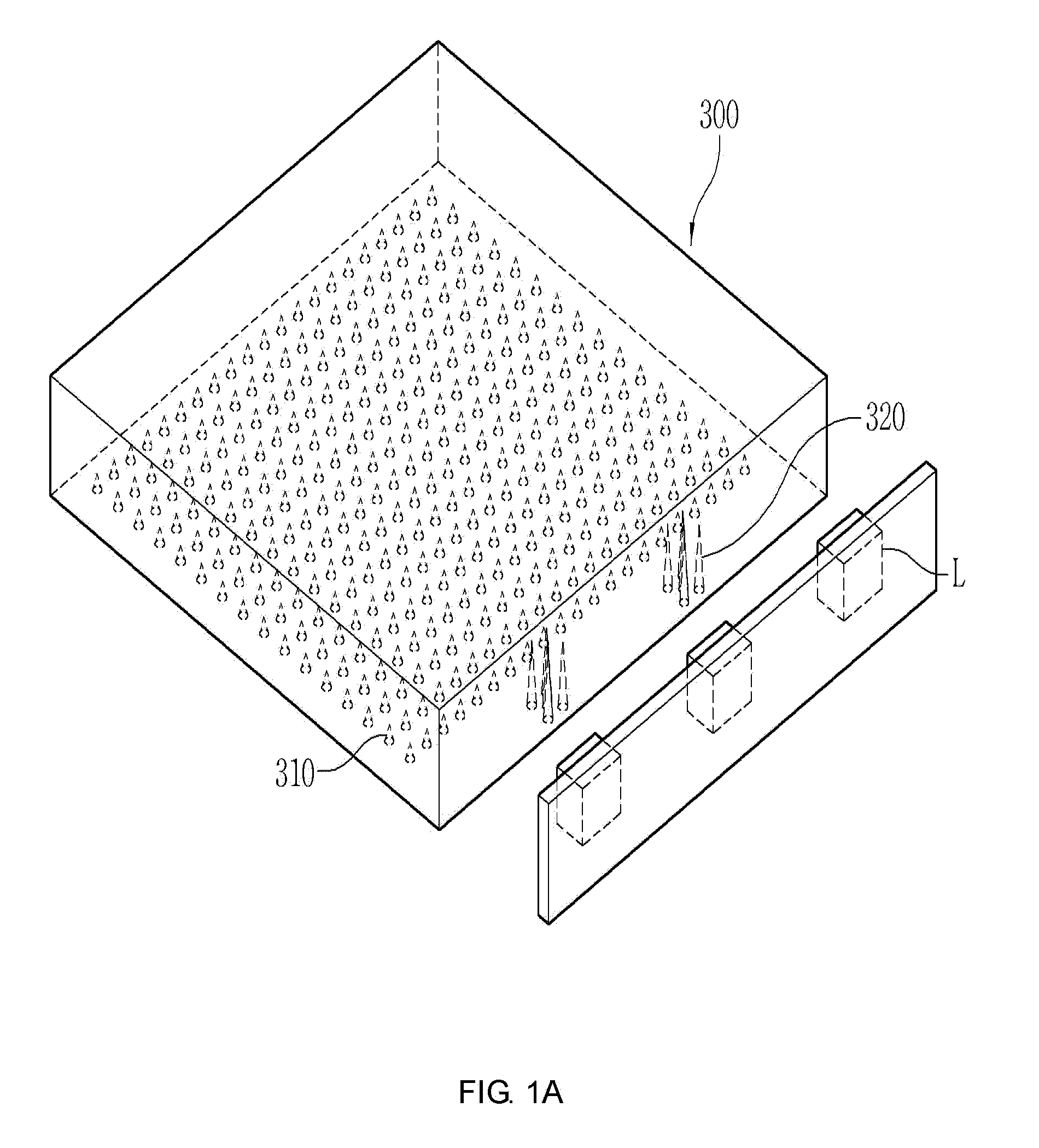
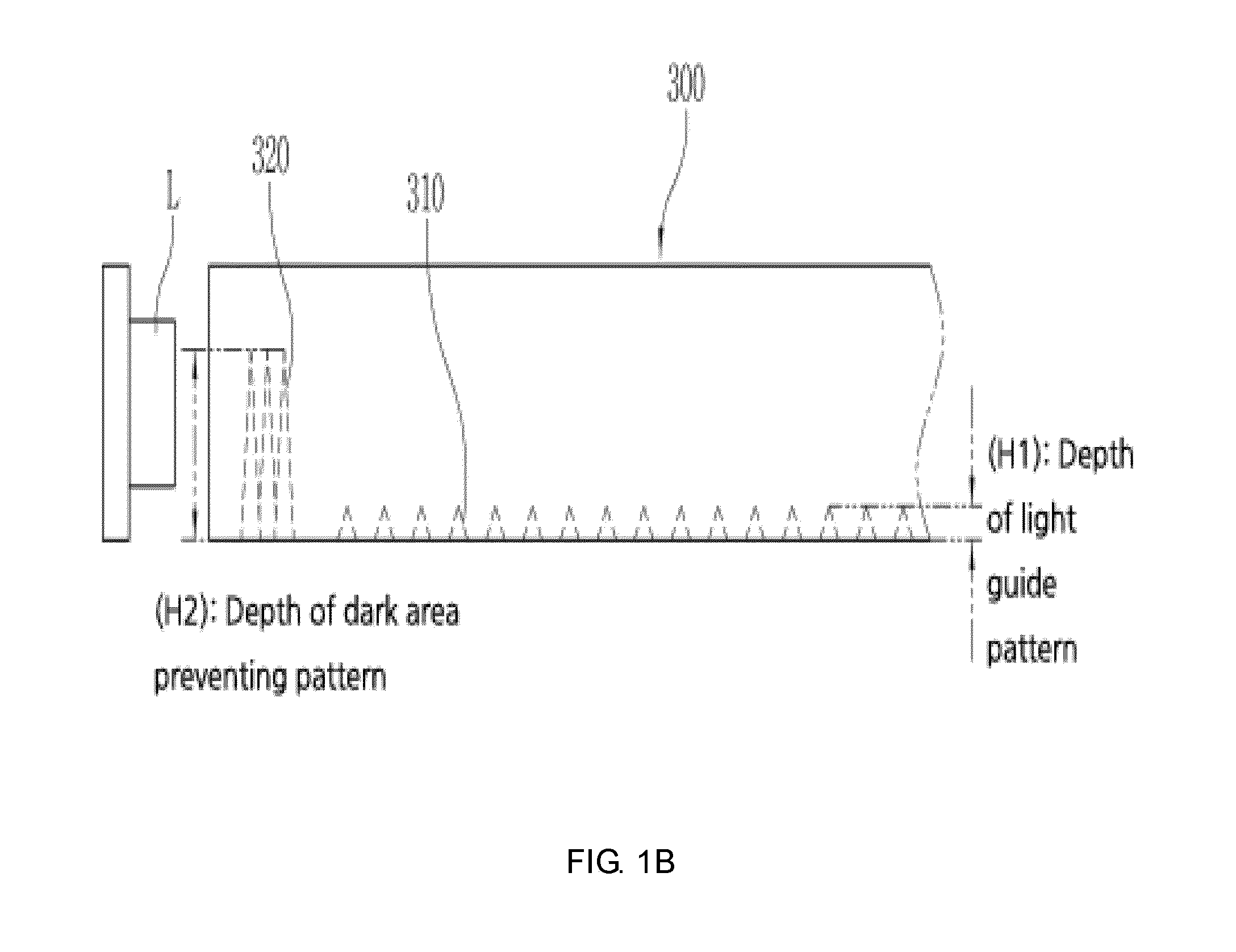
[0032]FIGS. 1A through 1C are a perspective view, a cross-sectional view, and a planar view, respectively, of the core part of a backlight unit, illustrating a light guide plate 300 and LEDs (L) according to the Embodiment 1 of the present invention.

[0033]Referring to FIGS. 1A to 1C, the backlight unit according to the Embodiment 1 of this invention shall have dark area-preventing patterns 320 formed at an edge of the light guide plate 300 corresponding to the gap between the LEDs (L) to prevent a dark area.

[0034]Here, the light guide plate 300 may be made of transparent synthetic resin allowing a light to penetrate in that it may be fabricated combining at least one of high-transparent silicone resin, urethane, polystyrene (PS), polycarbonate (PC), polyethylene terephthalate (PET), styrene methyl methacrylate (MS), and polymethyl methacrylate (PMMA).

[0035]A side plane facing the LED light source (L) among the planes of the light guide plate 300 is to be the incidence plane. Either ...

embodiment 2

[0051]FIGS. 4A through 4C are a perspective view, a cross-sectional view, and a planar view, respectively, of a backlight unit, illustrating a light guide plate 600 and LED light sources (L) according to the Embodiment 2 the present invention.

[0052]Referring to FIGS. 4A through 4C, the backlight unit according to the Embodiment 2 of the present invention is identical to the backlight unit depicted in FIG. 1A through 1C except those facts that a plurality of dark area-preventing patterns 620 shall be formed on an incidence plane of the light guide plate 600 corresponding to the gap between the LEDs (L) and the depth direction of the dark area-preventing patterns 620 is perpendicular to the depth direction of the light guide patterns 610.

[0053]When the dark area-preventing patterns 620 are formed as such on the incidence plane of the light guide plate 600 corresponding to the gap between the LEDs, only a small amount of light may have an intense light emitting effect due to the dark a...


PUM


Abstract

A backlight unit with a light guide plate preventing a dark area between LEDs is provided, wherein dark area-preventing patterns may adequately compensate for the brightness in a gap between the LEDs that may be a dark area even under the condition that the gap is relatively large and greater than or equal to the width of an LED and thus, uniform brightness may be obtained without an occurrence of the dark area. Accordingly, the number of the LEDs may decrease and thus, a large-sized backlight unit may be fabricated with a relatively low cost.

Description

CROSS REFERENCE[0001]Applicant claims foreign priority under Paris Convention to Korean Patent Application No. 10-2013-0046455 filed 26 Apr. 2013, with the Korean Intellectual Property Office, where the entire contents are incorporated herein by reference.BACKGROUND OF THE INVENTION[0002]1. Field of the Invention[0003]The present invention relates to a backlight unit with a light guide plate preventing a dark area between light emitting diodes (LEDs), and more particularly, to a technology for forming a plurality of dark area-preventing patterns at a position of a light guide plate corresponding to the gap between LEDs of an edge light type backlight unit and for obtaining uniform brightness without an occurrence of a dark area.[0004]2. Description of the Related Art[0005]In general, a light guide plate may refer to a plate providing a path through which a light irradiated from a light source is uniformly scattered and diffused and be applicable to a backlight unit (BLU) used for a ...

Claims


Application Information

Patent Timeline
IPC IPC(8): F21V8/00
CPCG02B6/0073G02B6/0018G02B6/0016G02B6/0036G02B6/0068
Inventor RHEW, CHOONGYOPPARK, DAISOUNGLEE, SEUNGKEUN
Owner HB TECH CO LTD
Why Eureka
Try Eureka