System, method, and apparatus for heating

a technology of system and method, applied in the field of system, method and apparatus for heating, can solve the problems of overestimation of the duration of the heating process, process to be completed, and use more energy than necessary, so as to improve the accuracy of the computed warm up time, avoid wasting energy, and minimize the running cost

Inactive Publication Date: 2014-10-30
OXFORD UNIV INNOVATION LTD
View PDF10 Cites 62 Cited by
  • Summary
  • Abstract
  • Description
  • Claims
  • Application Information

AI Technical Summary

Benefits of technology

[0101]Preferably the position and dispatch of thermal energy from the moveable heating element is optimised such that the user requirement is fulfilled and that minimal running cost is incurred for a given electricity tariff structure.
[0102]The controller comprises a current sensor and means of controlling the mains connection to the immersion element so that an embedded algorithm can determine the warm up time of a vessel's contents. This can be achieved by inspection of the current flowing through the immersion element. The controller can infer when tank is hot from monitoring the current, and the pattern of switching on / off. The immersion controller can be readily fitted to an existing immersion heater and hot water tank. The algorithm uses the computed warm up time to schedule the connection of the immersion element to a power supply just in time to meet the user's temperature requirements to avoid wasting energy. The immersion controller can be supplemented by a sensor(s) which measure the temperature of the surroundings of the vessel in order to improve the accuracy of the computed warm up time of the vessel's contents. The immersion controller can have the capability of informing the user when the immersion element has heated the contents of its associated vessel to the desired temperature, using some form of user interface. The immersion controller can have the capability of informing the user of the amount of energy which has been consumed by the immersion element, by inspection of the current flowing through the immersion element, using some form of user interface. As users often err toward overestimation of the warm up time, the controller can help avoid substantial standing losses.
[0103]The heating system comprises a moveable heating element within a vessel whose position is controlled continuously to optimise the dispatch of thermal energy to a liquid. A control algorithm determines the optimum position of the moveable heating element according to a combination of parameters such as temperature, heating element power dissipation, heating element current profile and vertical position of moveable heating element assembly. In one embodiment, the moveable heating element is tethered to a control assembly which adjusts the tether length via positional control of a winding drum to which the tether is attached in order to control the vertical position of the moveable heating element. Such an arrangement can be retrofitted to existing domestic hot water cylinders by designing in such a way as to ensure that both the control assembly and the moveable heating element can fit through a standard immersion element tank flange. In another embodiment, the vertical position of the moveable heating element is controlled via the angular position of a motorised ball screw whose axis is parallel to or collinear with the vertical axis of the vessel. The position and dispatch of thermal energy from the moveable heating element is optimised such that the user requirement is fulfilled and that minimal running cost is incurred for a given electricity tariff structure.

Problems solved by technology

Users are likely to overestimate the duration of the heating process, causing the heating process to be completed before the hot water is required.
This results in using more energy than necessary to fulfil the user's needs.

Method used


Image

  • System, method, and apparatus for heating
  • System, method, and apparatus for heating
  • System, method, and apparatus for heating

Examples


Embodiment Construction

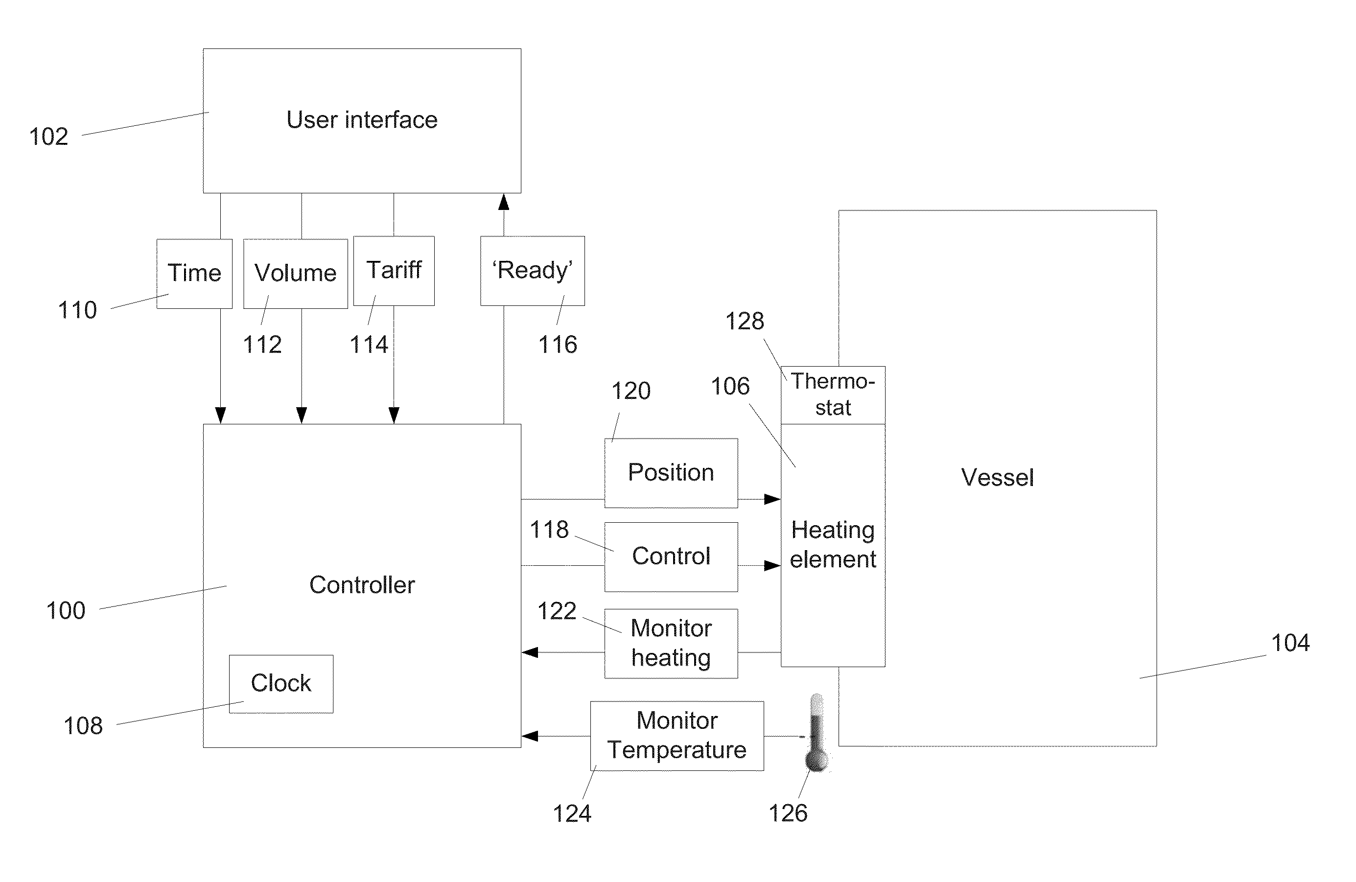
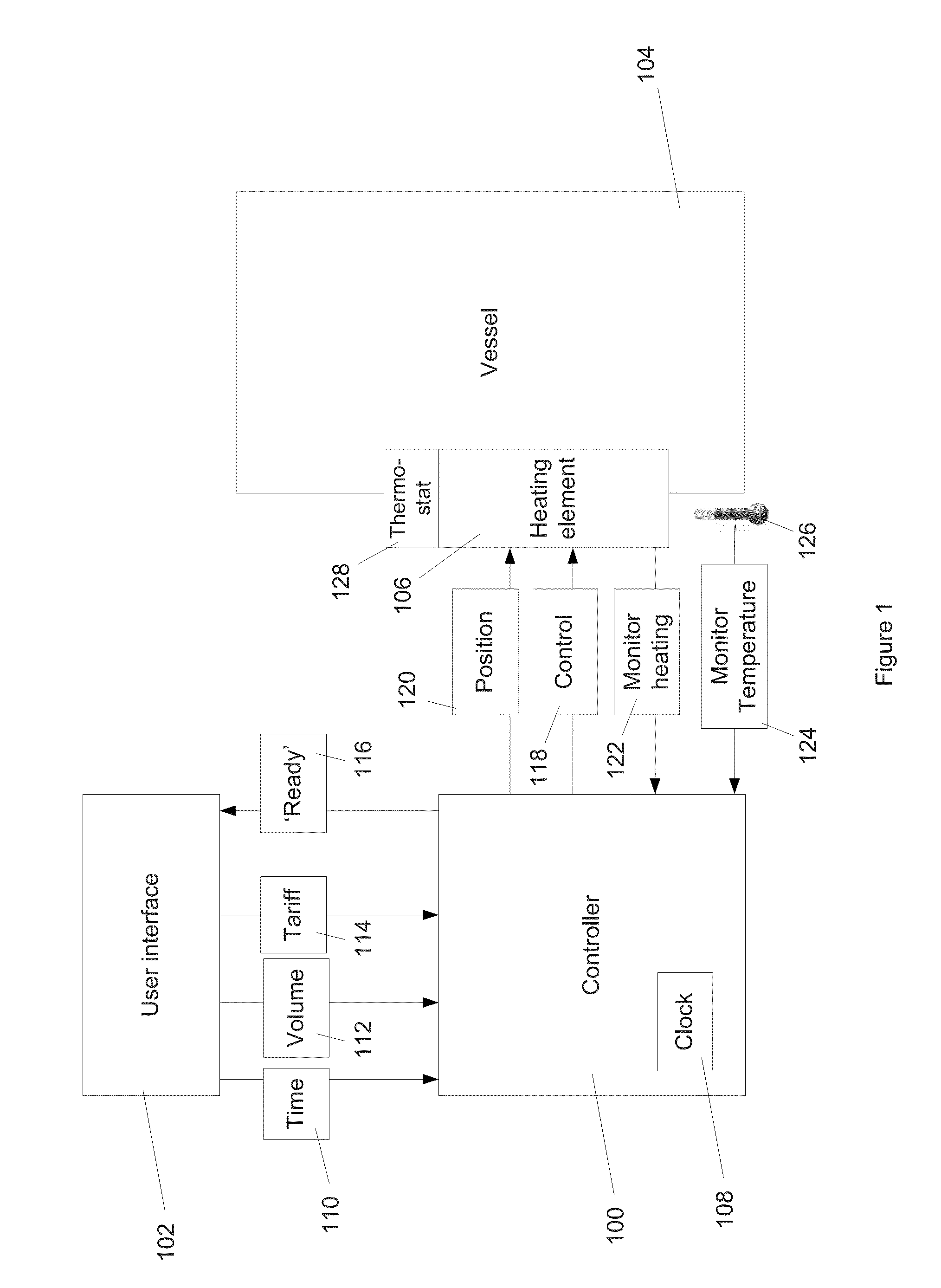
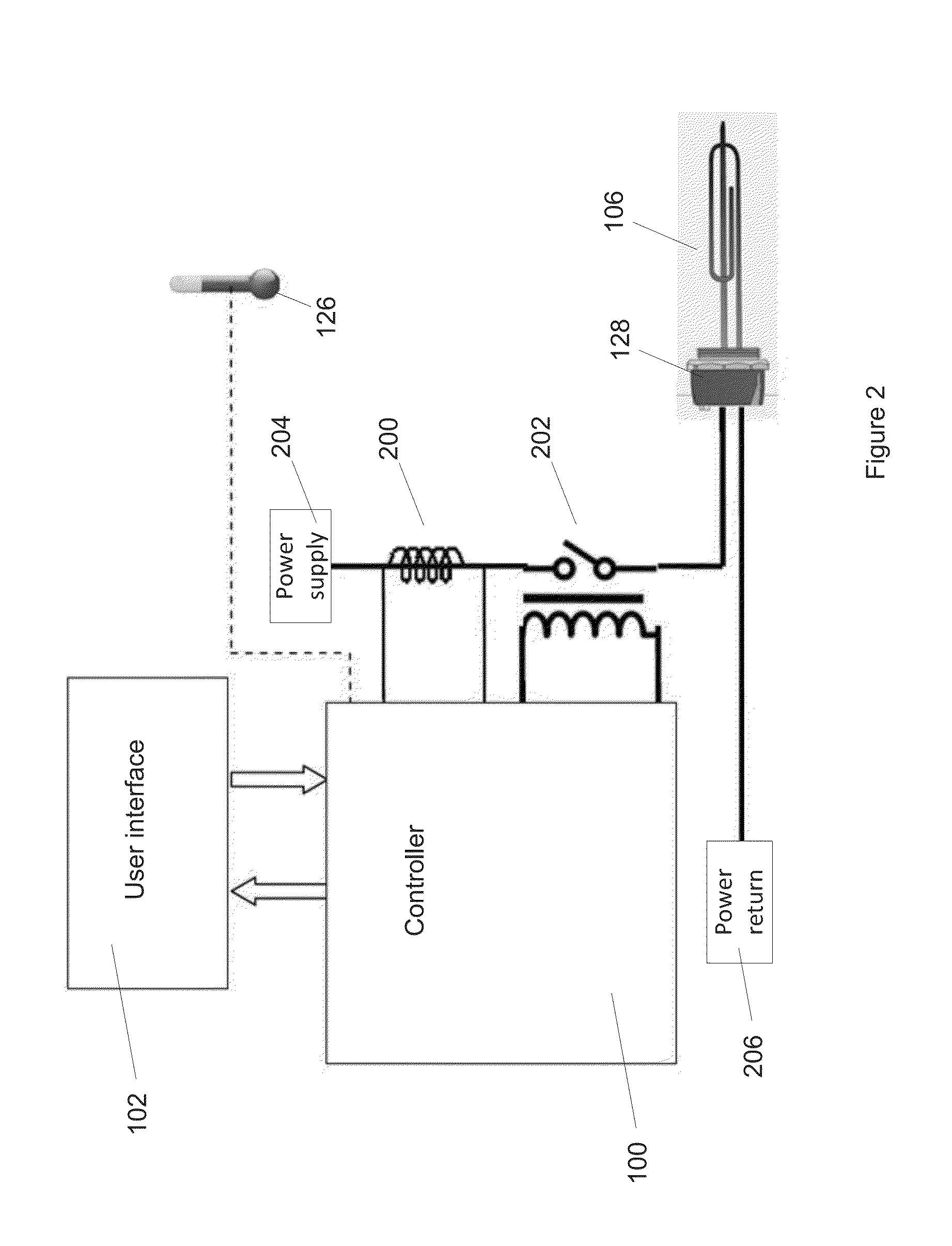
[0227]In reference to FIG. 1, a controller 100 monitors heating 122 of a heating element 106, for example by measuring the current flowing through an immersion element. This allows the controller 100 to detect when a vessel 104, typically containing hot water, has reached the desired temperature. An algorithm embedded within the immersion controller learns the time required for the vessel to reach the desired temperature, for example by inspection of the current waveform. The user of the controller programs, via a user interface 102, the required times 110 at which the vessel's contents are to be at some desired temperature. The user may input further variables, including volume 112 of water desired and information regarding energy tariffs 114. An algorithm embedded in the controller 100 calculates scheduling of the immersion element. This allows the controller 100 to control 118 heating, in particular initiating and terminating heating, for example by control of the power supply to...


PUM


Abstract

The present invention relates to a heating element controller 100 for a liquid heating system arranged to determine the duty cycle of a heating element 106 and modulate the timepoint of heating initiation by the heating element 106 in dependence upon an expected duration of completing the heating process and upon a required time at which the heating process is to be completed, wherein said expected duration is determined in dependence on said duty cycle. The invention extends to a heating element controller comprising means for computing a fouling parameter and means for controlling the operation of the heating element in dependence upon the fouling parameter. The invention extends to a system for heating liquids comprising at least one heating element associated with a liquid vessel, and preferably the heating element is moveable in the vessel, or alternatively the system for heating liquids may comprise a plurality of heating elements.

Description

[0001]The present invention relates to a heating element controller for a liquid heating system. The invention further relates to a system for heating liquids. Another aspect of the invention relates to a plume entrainment unit for liquid heating systems. The invention further relates to a method of controlling a heating element for a liquid heating system. Another aspect of the invention relates to a device for heating liquids in a heating vessel.BACKGROUND OF THE INVENTION[0002]Domestic hot water (DHW) systems are typically serviced entirely or are supplemented by an electric immersion element in a hot water tank. The element comprises of a resistive wire which dissipates heat as current flows through it. Usually, an integrated thermostat is fitted to the unit. The thermostat allows the user to set the temperature (typically 50 to 60° C.). Whilst this temperature is too high for direct use in most DHW applications, (i.e. the hot water has to be mixed with cold to deliver a comfort...

Claims


Application Information

Patent Timeline
Patent Type & Authority Applications(United States)
IPC IPC(8): F24H9/20F24H9/18
CPCF24H9/1818F24H9/2021F24H9/0015G05D23/1923G05D23/1951Y04S10/30Y04S20/244Y04S40/126F24H1/182F24H1/202F24D17/0073F24D19/1063F24D2200/08H02J2310/64F24D2240/26H02J13/00002H02J13/00024H02J13/00026Y02B70/30Y02B90/20Y02E60/00Y04S50/10Y04S20/221Y04S20/222Y02B70/3225G01K1/143Y02B30/70F24H9/28F24H15/421F24H15/156F24H15/225F24H15/25F24H15/128F24H15/281F24H15/254F24H15/269F24H15/144F24H15/37F24H15/486F24H15/288F24H15/172F24H15/104F24H15/219F24H15/395F24H15/20F24H15/277F24H15/215F24H15/174F24H15/14
Inventor ARMSTRONG, PETER MICHAEL
Owner OXFORD UNIV INNOVATION LTD
Why Eureka
Try Eureka