Flexible allocation of I/O channels of a hardware component

a hardware component and flexible technology, applied in the direction of instrumentation, program control, cad circuit design, etc., can solve the problems that the processor application cannot use the i/o channel with a set functional scope and a defined interface, and cannot be implemented practicably with cpu-based simulations

Active Publication Date: 2014-10-30
DSPACE DIGITAL SIGNAL PROCESSING & CONTROL ENG
View PDF5 Cites 8 Cited by
  • Summary
  • Abstract
  • Description
  • Claims
  • Application Information

AI Technical Summary

Benefits of technology

[0009]It is therefore an object of the present invention to provide a method that enables flexible use of the hardware component, whereby FPGA and processor can communicate with I / O channels during the execution and the available I / O channels of the hardware component can be freely allocated to the FPGA and processor.
[0011]In an embodiment, two applications are generated, one in the processor and one in the FPGA, which depending on the use allocate the I / O channels as desired to the two applications. The first application in the FPGA, also called the FPGA application below, thus only accesses the I / O channels which it needs for performing its tasks. The other I / O channels are provided via the communications interface in the second application in the processor, also called the processor application below. This enables a combination of a classic model-based generation of control, measurement, or regulation models with model-based generated FPGA models, which based on the FPGA technology enable short cycle times in the sub-microsecond range for regulation models or very high-performance signal preprocessing for measurement applications in a hardware component.
[0015]In an embodiment of the invention, the method comprises generating an application model, whereby the step of generating the first application comprises the model-based automatic generation of code. The modeling enables a simple code generation, whereby short development times are possible. Function blocks can be used to generate a desired functionality in the FPGA model-based in Matlab or Simulink. Further, the necessary I / O channels are preferably used in the application model and connected to a previously generated functionality.
[0017]In an embodiment of the invention, the step of generating code for connecting the second subset of I / O channels to the communications interface comprises providing pre-synthesized code for connecting I / O channels that are part of the second subset of I / O channels. The pre-synthesized code, moreover, makes it possible to reduce the time for generating the first application. The pre-synthesized code is part of the FPGA application, without it needing to be translated. The pre-synthesized code can be easily merged with other code elements, which is called fitting or place & route by different FPGA providers. Next, the code can be loaded in its entirety in the FPGA. The pre-synthesized code is preferably obtained from an available library.
[0020]In an embodiment of the invention, the method comprises the step of generating an application model, whereby the step of generating the second application comprises the model-based automatic generation of code. The modeling enables a simple code generation, whereby short development times are possible. Function blocks can be used to generate a desired functionality in the processor model-based in Matlab or Simulink. Further, the necessary I / O channels are preferably used in the application model and connected to a previously generated functionality.
[0024]Furthermore, the invention relates to a method for operating a hardware component of a measuring, control, or regulating system having a processor, an FPGA, and a plurality of I / O channels, whereby the I / O channels are connected to the FPGA and the FPGA is connected to the processor via a communications interface, the method comprising the loading of software generated according to the above method, and the execution of the software, whereby the loading of the software comprises loading of the first application into the FPGA and the loading of the second application into the processor. Accordingly, two applications, one on the processor and one in the FPGA, can be executed in the hardware component, which depending on the use allocate the I / O channels arbitrarily to the two applications. This enables the provision of a combination of classic control, measurement, or regulation models with model-based generated FPGA models, which based on the FPGA technology enable short cycle times in the sub-microsecond range for regulation models or very high-performance signal preprocessing for measurement applications in a hardware component.

Problems solved by technology

These can no longer be implemented practically with CPU-based simulations.
However, the processor application cannot use the I / O channels with a set functional scope and a defined interface.

Method used


Image

  • Flexible allocation of I/O channels of a hardware component
  • Flexible allocation of I/O channels of a hardware component
  • Flexible allocation of I/O channels of a hardware component

Examples


Embodiment Construction

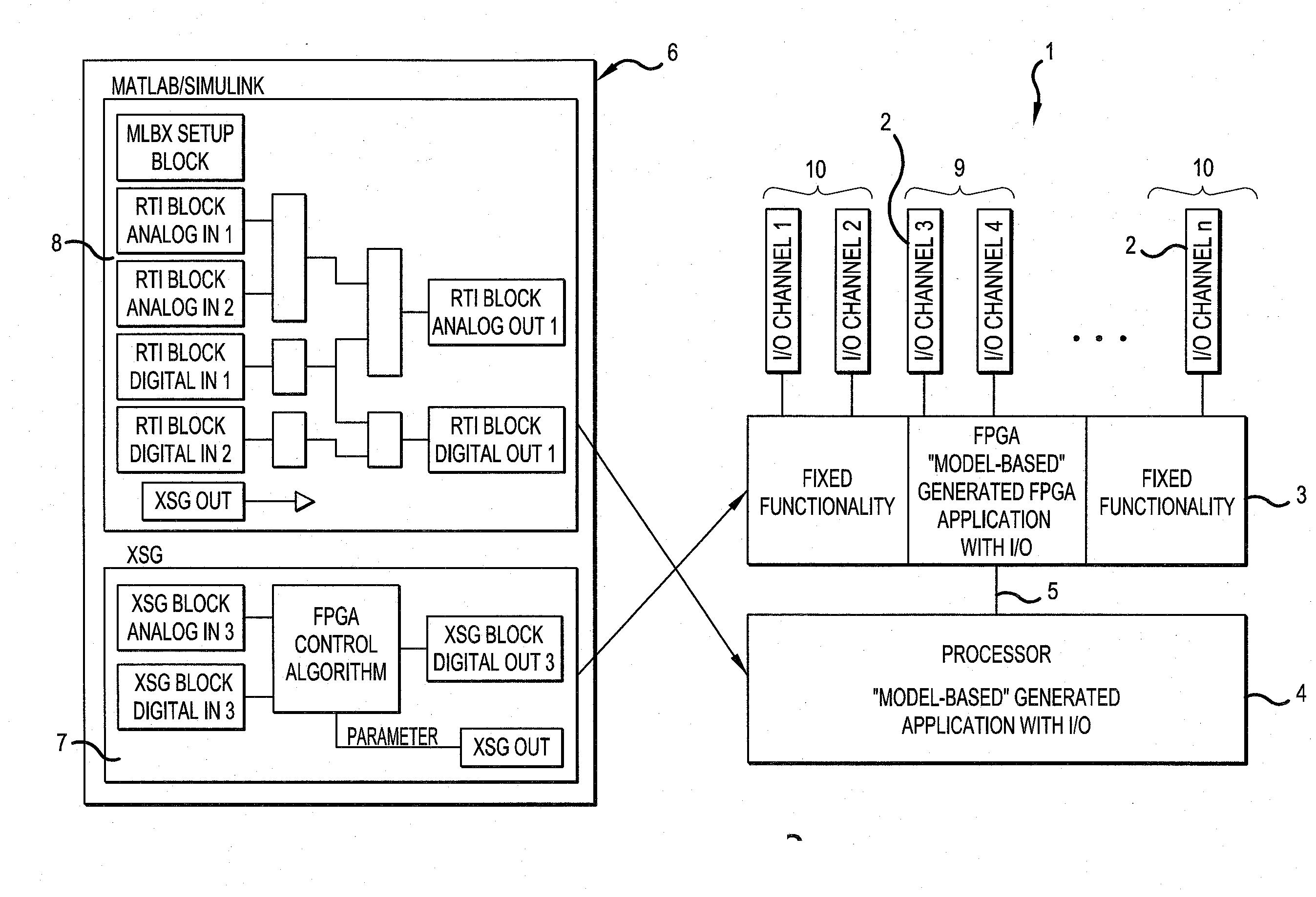
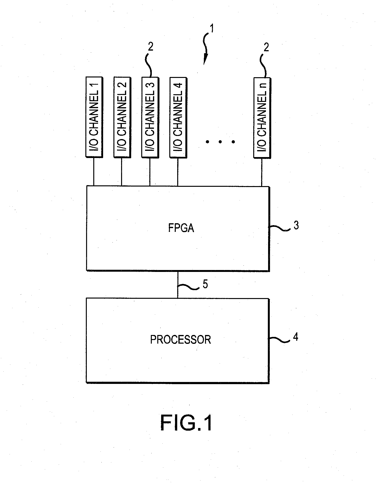
[0038]FIG. 1 shows a hardware component 1 of the measuring, control, or regulating system according to a first embodiment. The hardware component 1 here is by way of example a device for rapid control prototyping (RCP) and comprises a plurality of I / O channels 2, an FPGA 3, and a processor 4. I / O channels 2 are connected to FPGA 3 and FPGA 3 is connected to processor 4 via a communications interface 5. In this exemplary embodiment, hardware component 1 has as I / O channels 2 overall 24 ADCs, 16 DACs, and 48×DIO, which are shown only partially in FIG. 1.

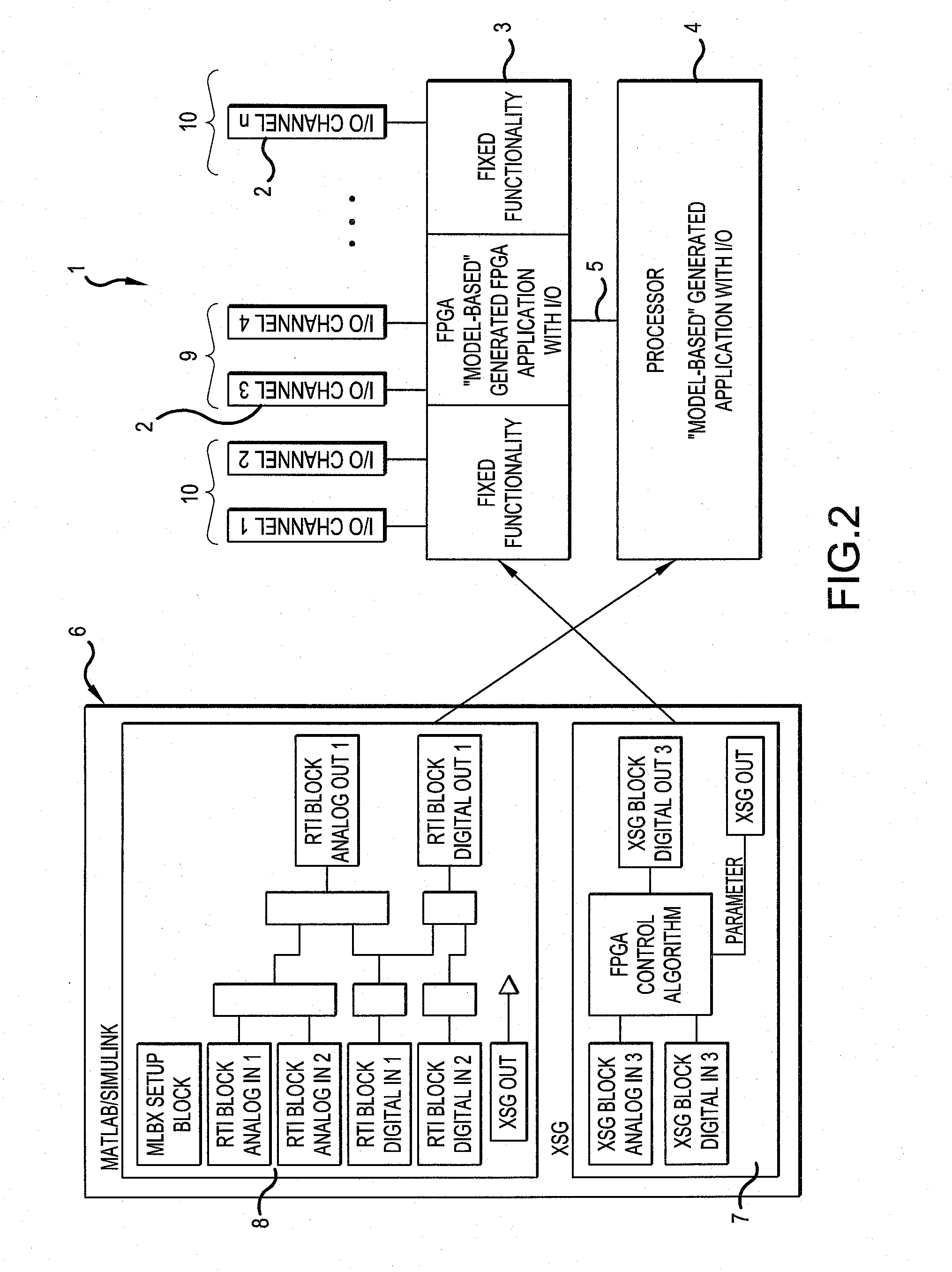
[0039]FIG. 2 shows in addition to hardware component 1 a data processing device 6, which is a powerful computer. As first software block 7 an FPGA programming blockset with a Simulink blockset for programming FPGA 3 and Xilinx Tools (ISE, XSG) for generating a first application for execution in FPGA 3 and as second software block 8 an RTI blockset or a Simulink blockset for generating a second application for execution on processor 4 a...


PUM


Abstract

A method for generating software for a hardware component of a measuring, control, or regulating system having a processor, an FPGA, and a plurality of I / O channels. The I / O channels are connected to the FPGA and the FPGA is connected to the processor via a communications interface. The method includes the steps of selecting a first subset of the I / O channels for operation by the FPGA, generating a first application for execution in the FPGA, selecting a second subset of the I / O channels for operation by the processor, and generating a second application for execution on the processor. The step of generating a first application comprises generating code for connecting the second subset of I / O channels to the communications interface. The invention relates in addition to a method for operating a hardware component.

Description

[0001]This nonprovisional application claims priority under 35 U.S.C. §119(a) to German Patent Application No. DE 10 2013 104 320.8, which was filed in Germany on Apr. 29, 2013, and which is herein incorporated by reference.BACKGROUND OF THE INVENTION[0002]1. Field of the Invention[0003]The present invention relates to a method for generating software for a hardware component of a measuring, control, or regulating system having a processor, an FPGA, and a plurality of I / O channels, whereby the I / O channels are connected to the FPGA and the FPGA is connected to the processor via a communications interface. Likewise, the invention relates to a computer program product with computer-implemented instructions, the product which after loading and execution in a suitable data processing device performs the steps of the above method, and a digital storage medium with electronically readable control signals, which can work together with a programmable data processing device, so that the abov...

Claims


Application Information

Patent Timeline
Patent Type & Authority Applications(United States)
IPC IPC(8): G06F9/455
CPCG06F9/455G06F8/35G06F17/5027G06F17/5054G06F15/7871G06F30/331G06F30/34
Inventor MERTEN, STEFANSCHLENGER, MARCROSS, HOLGERMERTENS, FRANK
Owner DSPACE DIGITAL SIGNAL PROCESSING & CONTROL ENG
Why Eureka
Try Eureka