Plastic-Rod-Screen-Fills for Use in Evaporative Water Cooling and Airborne Fumes Removal Apparatuses and Fabrication Thereof

a technology of evaporative water cooling and airborne fume removal, which is applied in the field of filling media of plastic rods, can solve the problems of high manufacturing cost that cannot be eluded, and achieve the effects of more rigid, stronger and more rigid, and stronger and more rigid

Inactive Publication Date: 2014-11-06
PARK CHONG MOOK
View PDF12 Cites 4 Cited by
  • Summary
  • Abstract
  • Description
  • Claims
  • Application Information

AI Technical Summary

Benefits of technology

[0030]<Effect of corrugated lines on surface of plastic rod> The plastic rods consisted of within the PRSF are thin in range of 2.5 to 15 mm in diameter, other diameter is possible, and it has spiral corrugated surface with a 3 to 10 lines on its surface. The spiral corrugated rod is schematically illustrated in FIG. 7. As shown in FIG. 7, the spiral corrugated lines are slanted to the length of rod. The spiral corrugated lines have effective slant angles of 10 to 30 degree to the length of the plastic rod. When the slant angle is greater than 35 degree, the water flowing on the surface of the plastic rod flows straightly down over the corrugated lines instead of flowing down along the corrugated lines, while the corrugated lines of slant angle less than 10 degree does not make a significant difference between the lengths of corrugated lines and plastic rod. The slant angles preferred in the present invention are 15 to 30 degree. While water is flowing down on the surface of the corrugated plastic rod, the water flows down along the corrugated lines, so that the water can flow on longer length by around 3 to 15% than on non-corrugated rod, since the

Problems solved by technology

By using such manufacturing lines of two step manufacturing, the mass produc

Method used


Image

  • Plastic-Rod-Screen-Fills for Use in Evaporative Water Cooling and Airborne Fumes Removal Apparatuses and Fabrication Thereof
  • Plastic-Rod-Screen-Fills for Use in Evaporative Water Cooling and Airborne Fumes Removal Apparatuses and Fabrication Thereof
  • Plastic-Rod-Screen-Fills for Use in Evaporative Water Cooling and Airborne Fumes Removal Apparatuses and Fabrication Thereof

Examples


Embodiment Construction

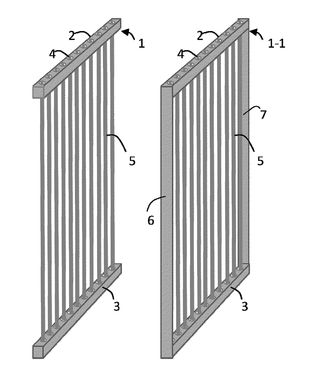
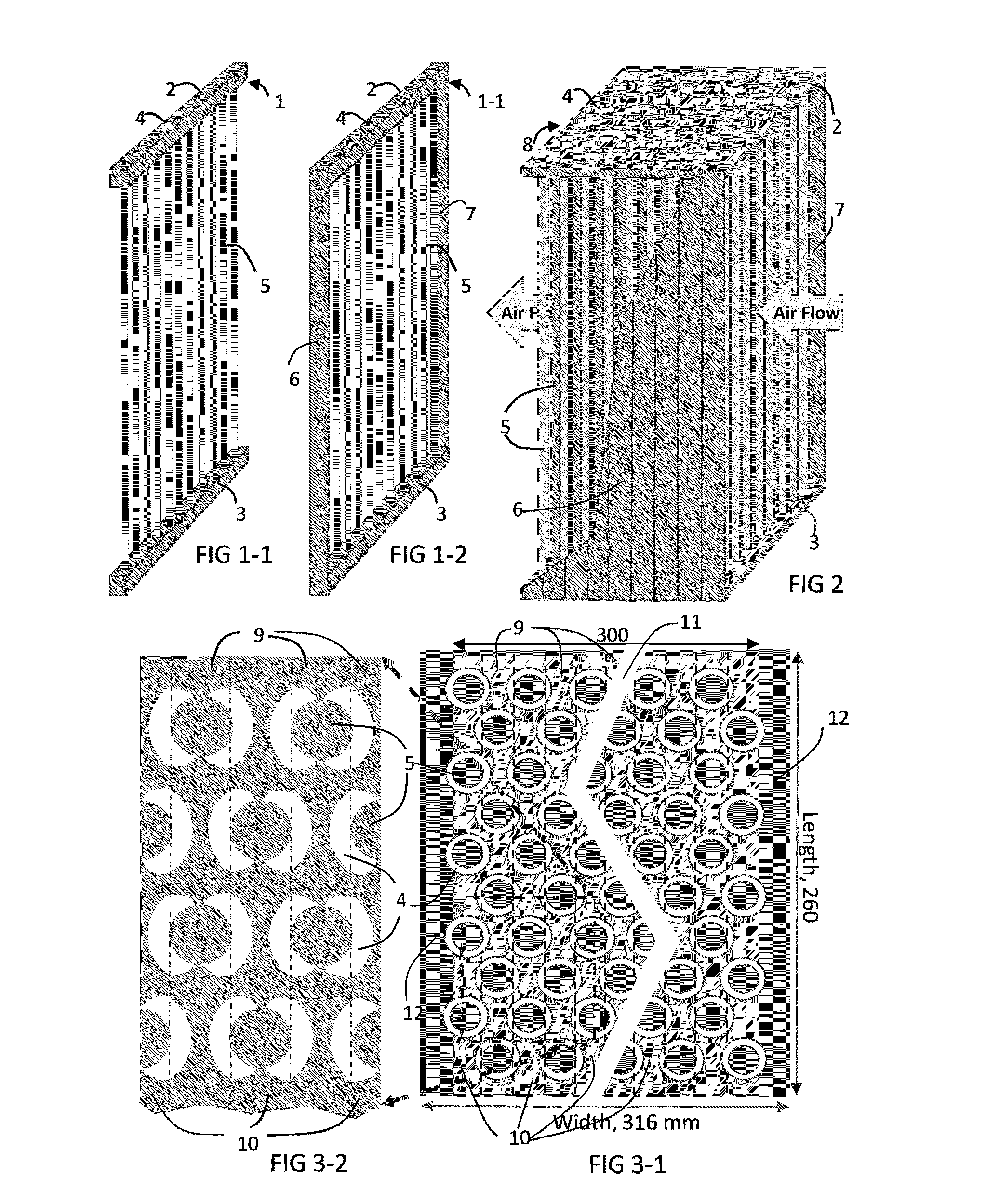
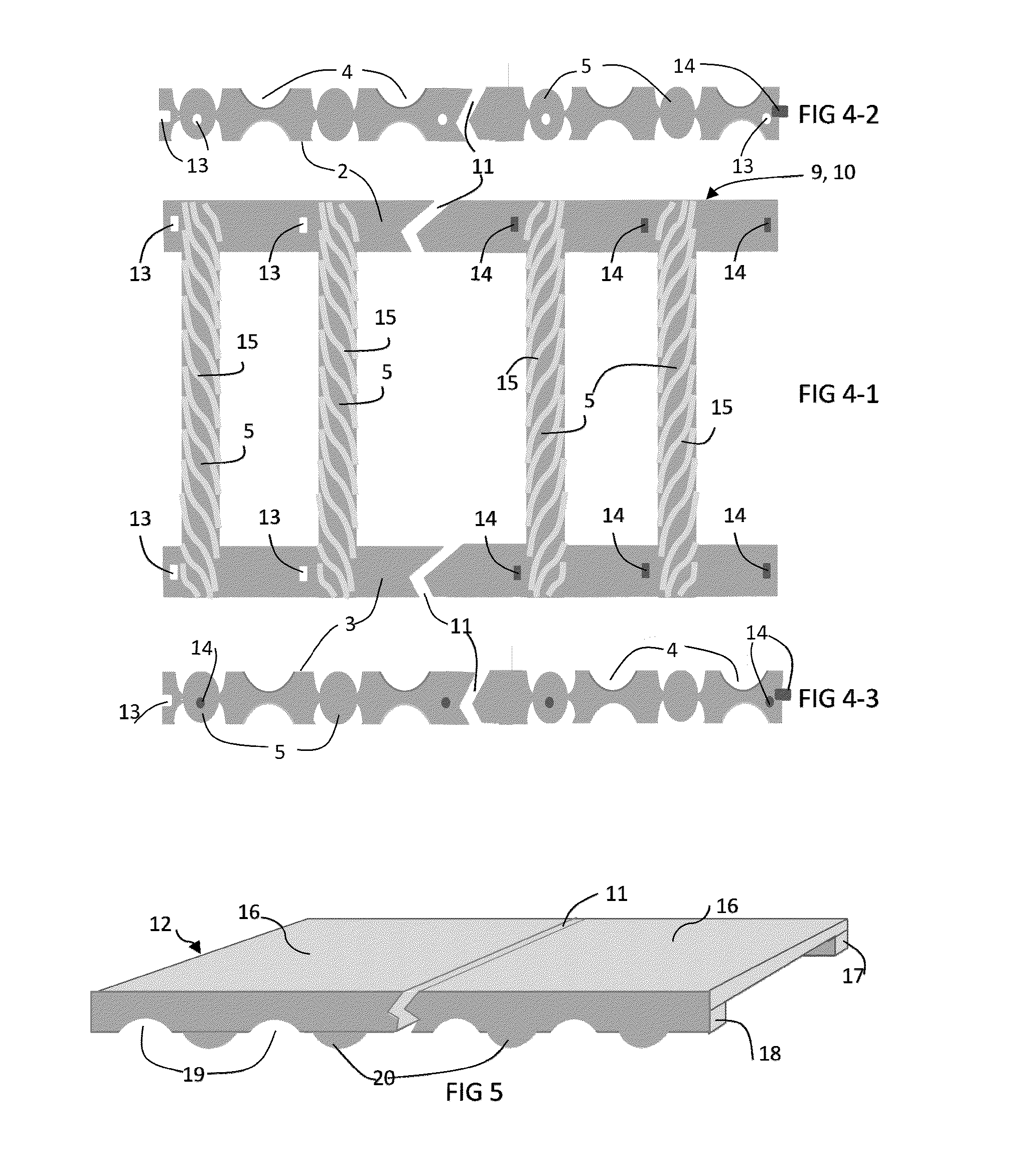
[0071]The string screen fills (SSFs) invented by the present inventor have a disadvantage in manufacturing of the SSFs, since they are fabricated through separated two manufacturing lines of molding fabrication of SSF frame and webbing fabrication of winding strings over the SSF frame. Such manufacturing lines have a problem limiting more reduction of the manufacturing cost of SSFs. To complement such a problem, a one step manufacturing line, described above, of the present invention is invented. One step manufacturing means a manufacturing of SSF frame and string winding over the frame within one manufacturing line at a same time instead of individual fabrication through two different manufacturing lines, In other word, the SSF frame and loading string on the frame are completely accomplished in one step same manufacturing. Therefore, one step manufacturing line can reduce by nearly one half of manufacturing time and cost required in the previous manufacturing process claimed in US...


PUM


Abstract

The present invention involves plastic-rod-screen-fills for use as fill media in any evaporative water cooling and airborne fumes removal apparatuses. The plastic-rod-screen-fill consists of top and bottom frames and several plastic rods suspending from between the top and bottom frames in the shape of a rectangular thin plate as a rod screen. The plastic rods are separated sufficiently apart from each other in one layer and parallel to the length of the rectangular plastic-rod-screen-fill. The plastic rods and top and bottom frames are in one structure. Plastic-rod-screen-fills are assembled by adjoining to each other to fabricate the plastic-rod-screen-fills pack and designed to be installed upright or slantly in the evaporative cooling apparatuses. The plastic-rod-screen-fills have high manufacturing and installation cost competition, compared with those of current film fills and string-screen-fills. The fabrication methods of plastic-rod-screen-fills and plastic-rod-screen fill packs are described in the present invention.

Description

CROSS-REFERENCE TO RELATED APPLICATIONReferences Cited[0001]U.S. patent documents;[0002]U.S. application Ser. No. 13 / 053,382, Mar. 22, 2011. Park[0003]U.S. Application No. 61 / 726,928, Nov. 21, 2012. Park[0004]U.S. Application No. 61 / 736,646, Dec. 13, 2012. ParkForeign Patent Documents[0005]KR100393126Jul. 18, 2003ParkKR100516391Sep. 14, 2005ParkKR100516392Sep. 14, 2005ParkPCTWO 2005 / 008159 A1Jan. 27, 2005ParkOther Publications[0006]Dominick V. Rosato. et al, Injection Molding Handbook, 3rd Edition, Kluwer Academic Publishers. Norwell, Mass. 02061, USA[0007]Robert A. Malloy, Plastic Part Design for Injection Molding An Introduction, Department of Plastic Engineering, University of Massachusetts, Lowell, Mass. 01854, USA[0008]Http: / / dehwa.comne.kr / mold / mold.htmSTATEMENT REGARDING FEDERALLY SPONSORED RESEARCH OR DEVELOPMENT[0009]Not Applicable.REFERENCE TO SEQUENCE LISTING, A TABLE, OR A COMPUTER PROGRAM LISTING COMPACT DISC APPENDIX[0010]Not Applicable.BACKGROUND OF THE INVENTION[0011...

Claims


Application Information

Patent Timeline
IPC IPC(8): F24F6/02
CPCF24F6/02F24F5/0035F28D5/02F28F25/087Y02B30/54
Inventor PARK, CHONG MOOK
Owner PARK CHONG MOOK
Why Eureka
Try Eureka