
Plug device for contact-free inductive energy transfer and operating method for such a plug device

Active Publication Date: 2014-11-06
WEIDMULLER INTERFACE GMBH & CO KG
View PDF2 Cites 2 Cited by
  • Summary
  • Abstract
  • Description
  • Claims
  • Application Information

AI Technical Summary

Benefits of technology

The invention relates to a connector device for contactless energy transfer between parts. It uses a primary coil and a secondary coil connected through a ferrite core. The ferrite core increases the magnetic flux, allowing for higher power transfer even at small sizes and gaps between parts. The device is also designed to minimize power loss due to re-magnetization processes and maximize efficiency. Additionally, the device includes a thermal connection between the electronic components and the ferrite core, which increases the overall efficiency of the device. Furthermore, the invention provides a method preventing energy transfer based on operating factors of the primary coil, ensuring safety and preventing hazards from the primary part.

Problems solved by technology

In addition, the risk of the formation of light arcs at the time of the disconnection of the connectors under a high current load does not exist with contact-free connector devices.

Method used


Image

  • Plug device for contact-free inductive energy transfer and operating method for such a plug device
  • Plug device for contact-free inductive energy transfer and operating method for such a plug device
  • Plug device for contact-free inductive energy transfer and operating method for such a plug device

Examples


Embodiment Construction

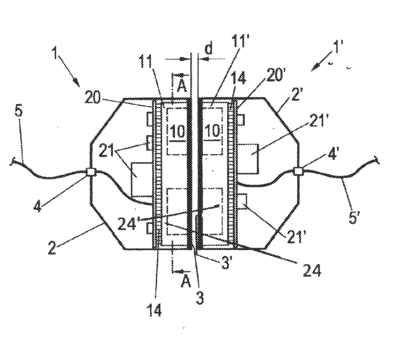
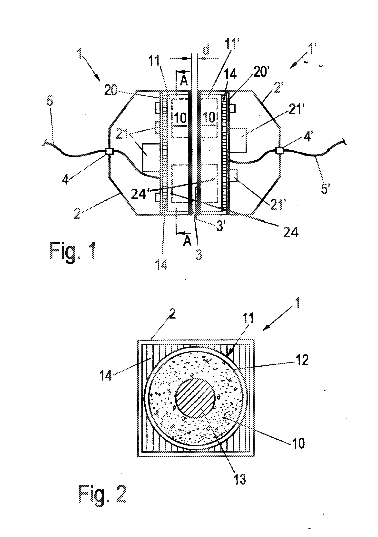
[0022]Referring first more particularly to FIGS. 1 and 2, the connector arrangement of the present invention includes a pair of primary and secondary connector components 1 and 1′ provided with generally half-shell shaped housings 2, 2′ containing chambers that receive pot-shaped ferrite cores 11 and 11′, respectively. The housing chambers are closed by front plates 3 and 3′ that are parallel with the adjacent vertical faces of the cores when the components 1 and 1′ are arranged in spaced relation by the spacing distance d shown in FIG. 1. The core front faces contain annular recesses 24 and 24′ that define cylindrical central inner dome portions 13, 13′, and annular outer marginal wall portions 11, 11′. Arranged in the annular recesses, respectively, are annular coils 10 and 10′ that are connected with input and output cables 5 and 6 that extend through passages 4 and 4′ contained in the walls of the housings 2 and 2′ respectively. The coils 10 and 10′ can each be wound with an ind...


PUM


Abstract

A contact-free electrical connector arrangement is provided for transferring inductive energy from a primary connector component to a secondary connector component, comprising a pair of connector components each including a housing containing a chamber, a ferrite core arranged in the chamber, and a coil arranged in the chamber for cooperation with the core. An input cable supplies electrical energy to the coil contained in the housing of a primary one of said components, and an output cable removes inductively-transferred energy from the coil contained in the housing of a secondary one of said components. According to an operating method of the invention, a parameter is measured at the primary coil for interrupting the energy supply when the secondary component is not present.

Description

REFERENCE TO RELATED APPLICATIONS[0001]This application is a national stage under 35 U.S.C. 371 of PCT International Application No. PCT / EP2012 / 075189 filed Dec. 12, 2012, claiming priority of German application No. DE 10 2011 056 265.6 filed Dec. 12, 2011.BACKGROUND OF THE INVENTION[0002]1. Field of the Invention[0003]The invention relates to a connector device for contact-free energy transfer from a primary connector component to a secondary connector component, which components each have at least one coil, the connector components being inductively connected with each other. The invention moreover relates to an operating method for reliably operating such a connector device.[0004]2. Description of Related Art[0005]Compared to electrical connectors in which an energy transfer occurs via contact elements to be connected or disconnected, contact-free connector arrangements have advantages with regard to wear resulting from a high number of connection cycles or strong vibrations. In ...

Claims


Application Information

Patent Timeline
IPC IPC(8): H01F38/14
CPCH01F38/14
Inventor GRUENBERG, OLAFSTEINMETZ, ANDREAS
Owner WEIDMULLER INTERFACE GMBH & CO KG
Features
  • Generate Ideas
  • Intellectual Property
  • Life Sciences
  • Materials
  • Tech Scout
  • Unparalleled Data Quality
  • Higher Quality Content
  • 60% Fewer Hallucinations
Learn More