Power supply and storage device for improving drilling rig operating efficiency

a technology for drilling rigs and power supply devices, applied in the direction of transportation and packaging, ac-dc network circuit arrangements, ac-dc network load balancing, etc., can solve the problems of increasing the overall rig fuel consumption rate, increasing and increasing the demand for generators. , the effect of reducing the number of operating gensets

Inactive Publication Date: 2009-08-06
INR G LINKS
View PDF2 Cites 144 Cited by
  • Summary
  • Abstract
  • Description
  • Claims
  • Application Information

AI Technical Summary

Benefits of technology

[0019]It is an important feature of the invention that the system provided herein permits the reduction of the number of operating gensets on the rig. In practice, rigs have different numbers of generators typically 2 to 6. In some cases, less than all generators are in simultaneous operation. In other cases all generators may be run. This may be needed in periods of peak demand when the battery is at a low state of charge. That is, the present invention may actually increase the demand on the generators rather than reduce it. Specifically, the configurations of the present invention permit the generators to run at a higher state of efficiency. This is because the need for over capacity is reduced or eliminated by the peak shaving function of the power conditioner and energy storage device. Excess power is stored in the energy storage device during periods of off-peak demand and then used during periods of peak demand. Generators can then be started and stopped over longer time intervals to provide the average power requirement of the rig and the state of charge of the energy storage device.
[0020]In the past, the additional capacity was needed and had to be continuously operating because of the lag time in bringing up an additional genset from a dormant or an off condition. The storage/source system of the subject invention provides additional power on demand, eliminating the need to have ready reserve generatin...

Problems solved by technology

This significant increase in hydraulic horsepower results in a significant increase in the overall rig fuel consumption rate.
Over the last few decades, SCR and VFD rigs have become much more common and DC/DC and mechanical rigs are becoming scarce.
Typical operation of the rig results in a highly dynamic power consumption profile that leads to inefficiency.
Specifically, the rig power source has to be prepared to provide maximum power on demand and this means that during periods of low power consumption the rig power source is producing or has the capacity to produce more power than is required, making the operation inefficient.
In addition, the typical rig is configured to operate in a failsafe manner such that failure of a portion of the gensets will not shut down the rig.
This is critical because anytime a rig operation is shut down it is possible that the well will be lost.
At a minimum, hours to days of drilling time may be lost.
The typical genset configuration results in power factor inefficiencies which are roughly equal to the ratio of the actual output to the full voltage output capability.
This results in higher fuel consumption by running the engine (typically a diesel engine) at a lower than optimum efficiency.
In addition, many of the operational motors such as the mud pumps typically operate at high pressure (and high current) and speeds lower than rated.
Also, during periods of transient loads, it is not possible for the generation of power from the gensets to match the dynamic load of the operational equipment and dramatic power factor inefficiencies occur during the period required by the gensets to compensate for the changing load.
Without such contingencies any shut down of the rig can result in catastrophic consequences.
This solution was obviously not effective on single motor mud pumps, or when as commonly occurred, pumps had to be run at a ...

Method used


Image

  • Power supply and storage device for improving drilling rig operating efficiency
  • Power supply and storage device for improving drilling rig operating efficiency
  • Power supply and storage device for improving drilling rig operating efficiency

Examples


Embodiment Construction

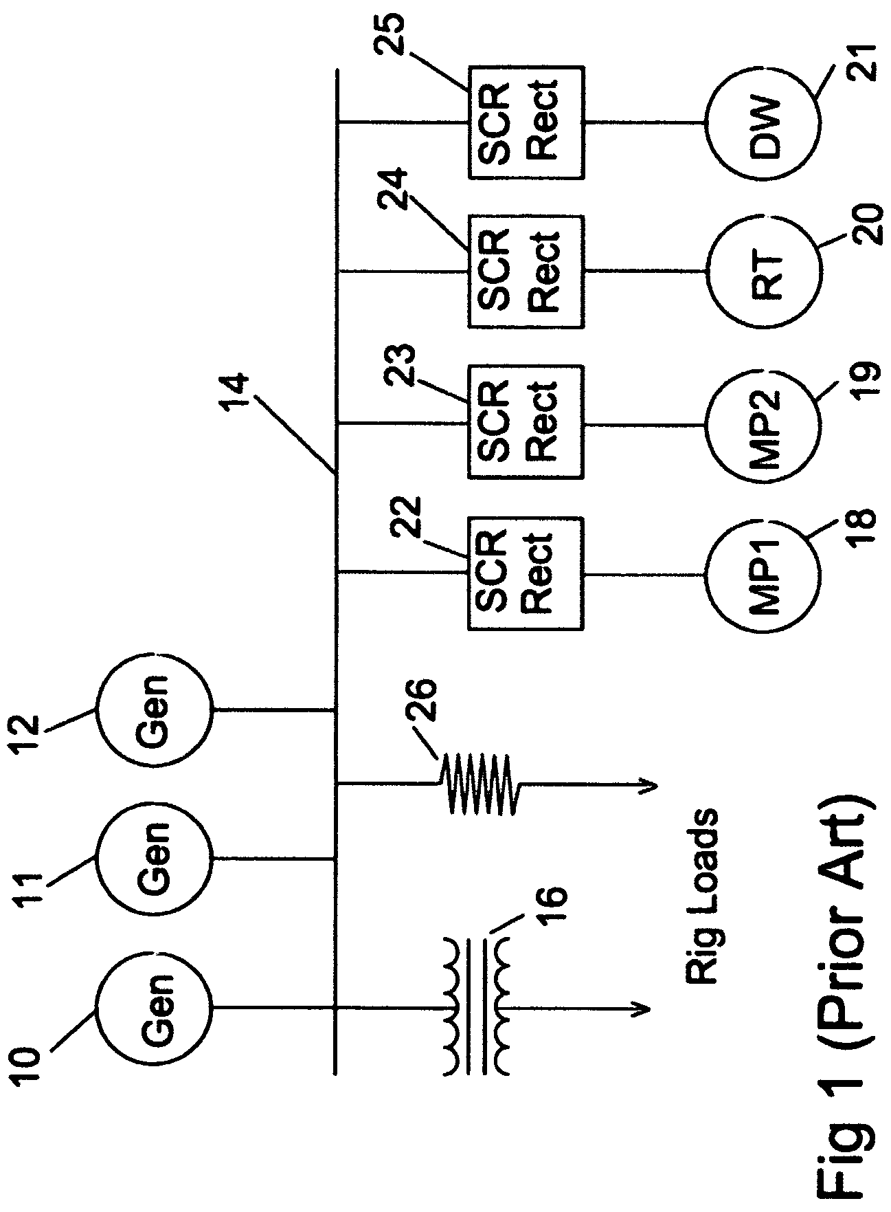
[0036]With reference to the PRIOR ART system of FIG. 1, the typical rig power supply circuit comprises two or more generators 10, 11 and 12 typically coupled by a bus 14 to various rig loads as indicated at 16 and rig motors such as indicated at 18, 19, 20 and 21. It should be understood that the number of generators is arbitrary depending upon rig configuration. In the embodiment shown the rig motors are connected to the bus through dedicated AC / DC converter circuits 22, 23, 24 and 25, respectively. However, it should be understood that the prior art systems may also include an AC / DC converter and chopper circuit arrangement between the various motors and the bus. A braking resistor 26 is also part of the circuit and is connected to the bus. In operation, the generators operate at a selected level and the various loads and motors draw power as needed. Excess power is dissipated through the braking resistor.

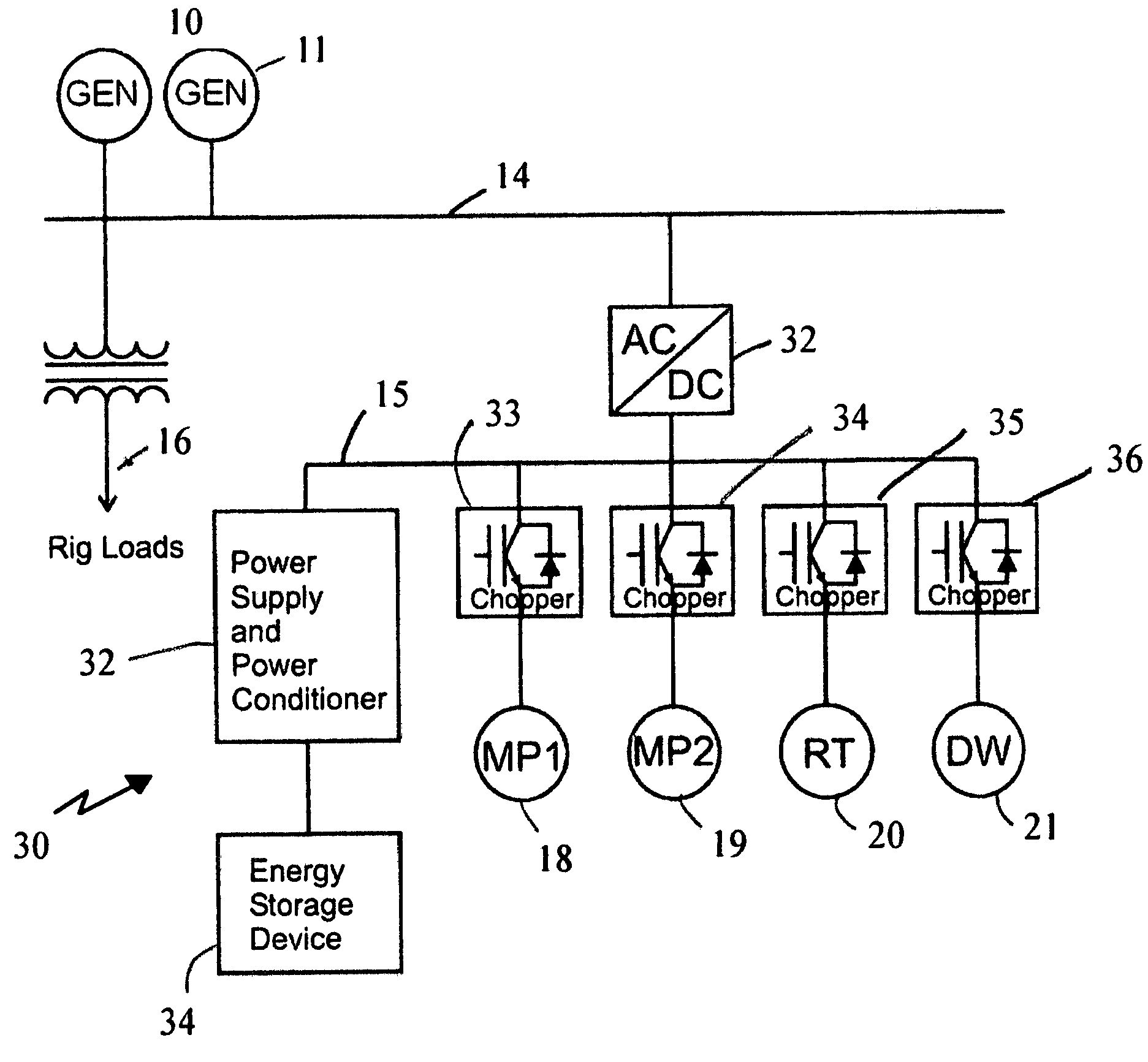
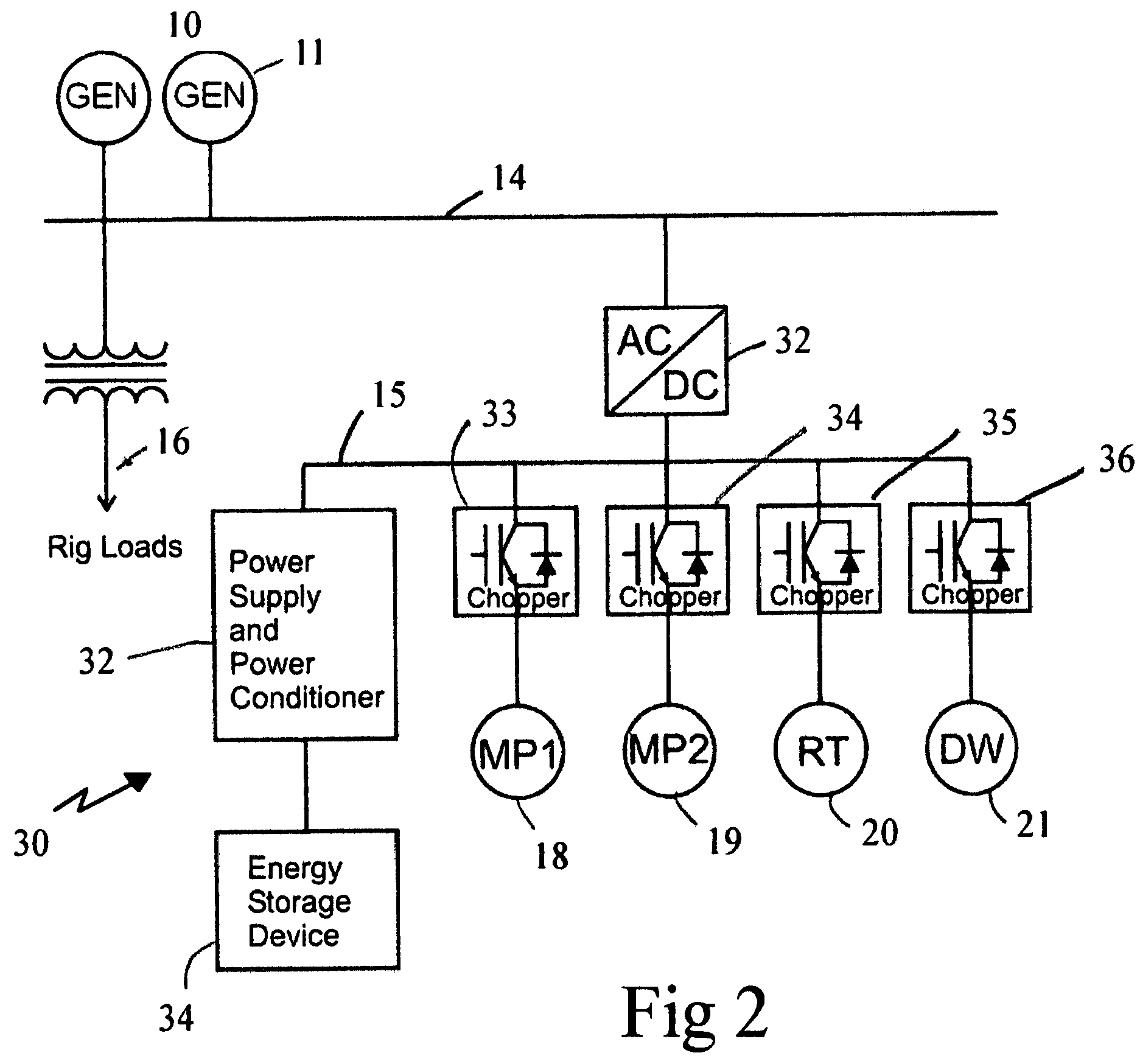
[0037]As shown in FIGS. 2-5, the storage / source system 30 of the subject inv...


PUM


Abstract

An energy supply and storage system for a rig power supply system is disclosed for a rig power supply system of the type having a power generator coupled to rig loads and motors via a bus. The energy supply and storage device is a power supply in parallel with the rig motors and adapted for receiving energy generated by the generator in excess of demand. The energy storage system is in communication with the power supply for receiving and storing the excess energy, with the power supply being adapted to draw energy from the storage system when the rig motor demand exceeds the capacity of the generator.

Description

BACKGROUND OF THE INVENTION[0001]1. Field of the Invention[0002]The present invention is generally related to power systems for drilling rigs and is specifically directed to an apparatus and a method for improving the efficiency of the conversion of chemical energy to electrical energy and for improving the energy efficiency of the rig through regeneration and improved power factors.[0003]2. Description of the Prior Art[0004]In the petroleum exploration industry the equipment used to bore wells for oil and gas recovery is commonly known as a drilling rig. Over the years, various types of rigs have been used by the industry and have been classified either by reference to the type of power used on board the rig to provide the motive force necessary to turn the drill bit or perform the other rig operations or as to the type of terrain on which the rig is situated. For example, a rig may be termed an “offshore” rig if it is one used for offshore drilling, but more commonly rigs are refe...

Claims


Application Information

Patent Timeline
IPC IPC(8): H02J7/34
CPCH02J3/28H02J7/34H02J4/00H02J2310/10
Inventor BUIEL, EDWARD R.
Owner INR G LINKS
Why Eureka
Try Eureka