
Master recombiner box with wireless monitoring capability

a recombiner box and wireless monitoring technology, applied in the field of components, can solve the problems of insufficient power production, reduced power production of a given solar field, and insufficient power production

Active Publication Date: 2014-11-06
SHOALS TECH GROUP
View PDF21 Cites 4 Cited by
  • Summary
  • Abstract
  • Description
  • Claims
  • Application Information

AI Technical Summary

Benefits of technology

The present invention is a device that combines and monitors the output of solar cells using a special assembly with multiple bus bars and sensors. The power from the solar field is combined and then transferred to an inverter where it is changed from DC to AC. The invention can monitor up to 20 different inputs from associated recombiner boxes, making it easy to detect any reduction in power output or areas of maintenance. The monitoring is performed using current transducers and a control circuit board that sends the data to a computer on site or internet for evaluation. The monitoring system is powered by an external power supply, and a ground wire is routed for each combiner box circuit. The technical effect of this invention is to provide a more efficient and effective way to monitor and manage solar power production.

Problems solved by technology

A variety of problems may decrease the power production of a given solar field.
For example, individual solar collectors may be damaged, shaded, or have faulty connections such that power is not produced, is inadequately produced, or the generated power never makes it to the collector.
Unfortunately however, this known technology is unable to handle high current, defined here as 100-600 amps.
Combiner box level disruptions are significant, and negatively affect the overall production and efficiency of the solar field.

Method used


Image

  • Master recombiner box with wireless monitoring capability
  • Master recombiner box with wireless monitoring capability
  • Master recombiner box with wireless monitoring capability

Examples


Embodiment Construction

[0022]In the following description, like reference characters designate like or corresponding parts throughout the several views.

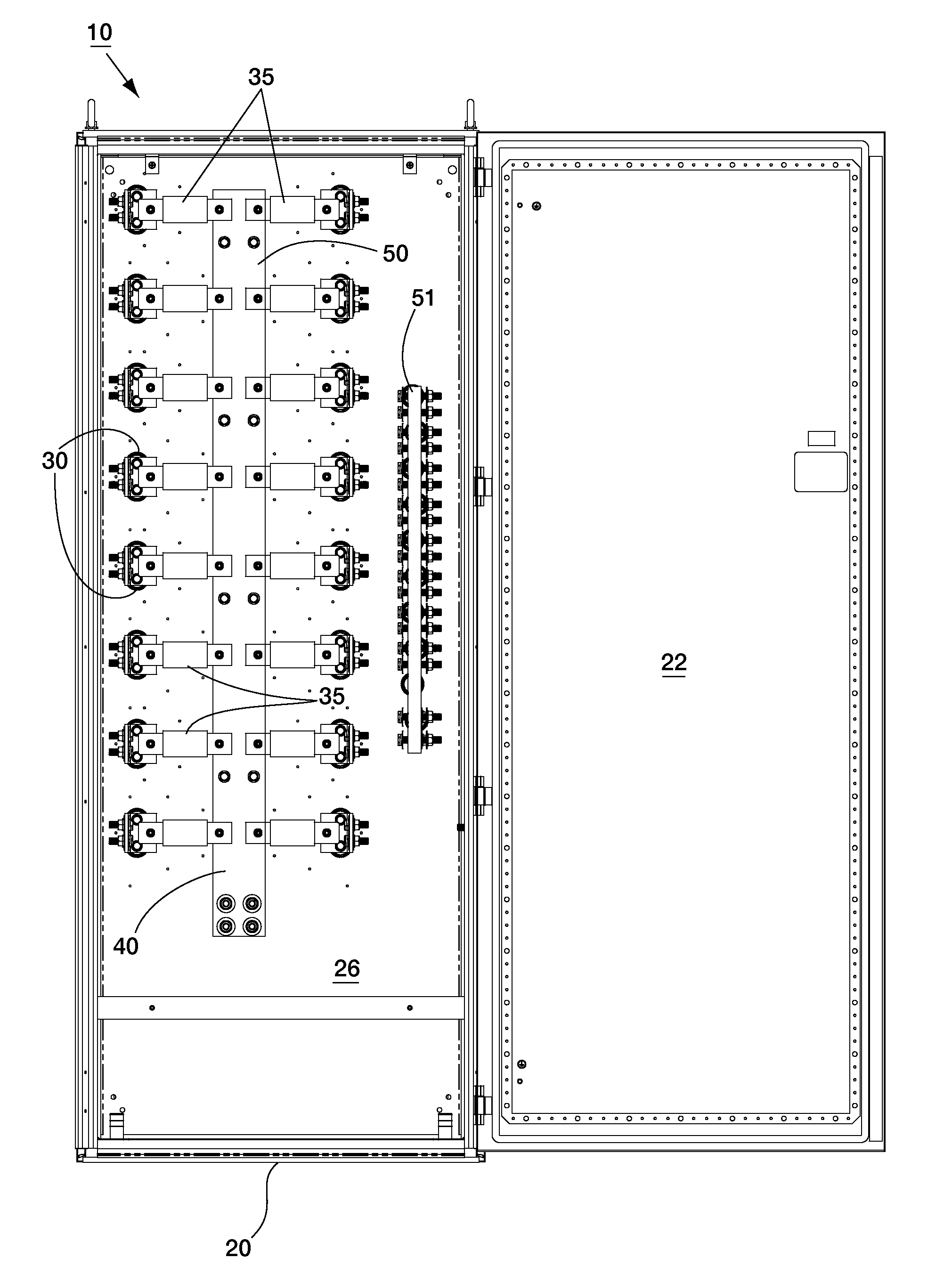
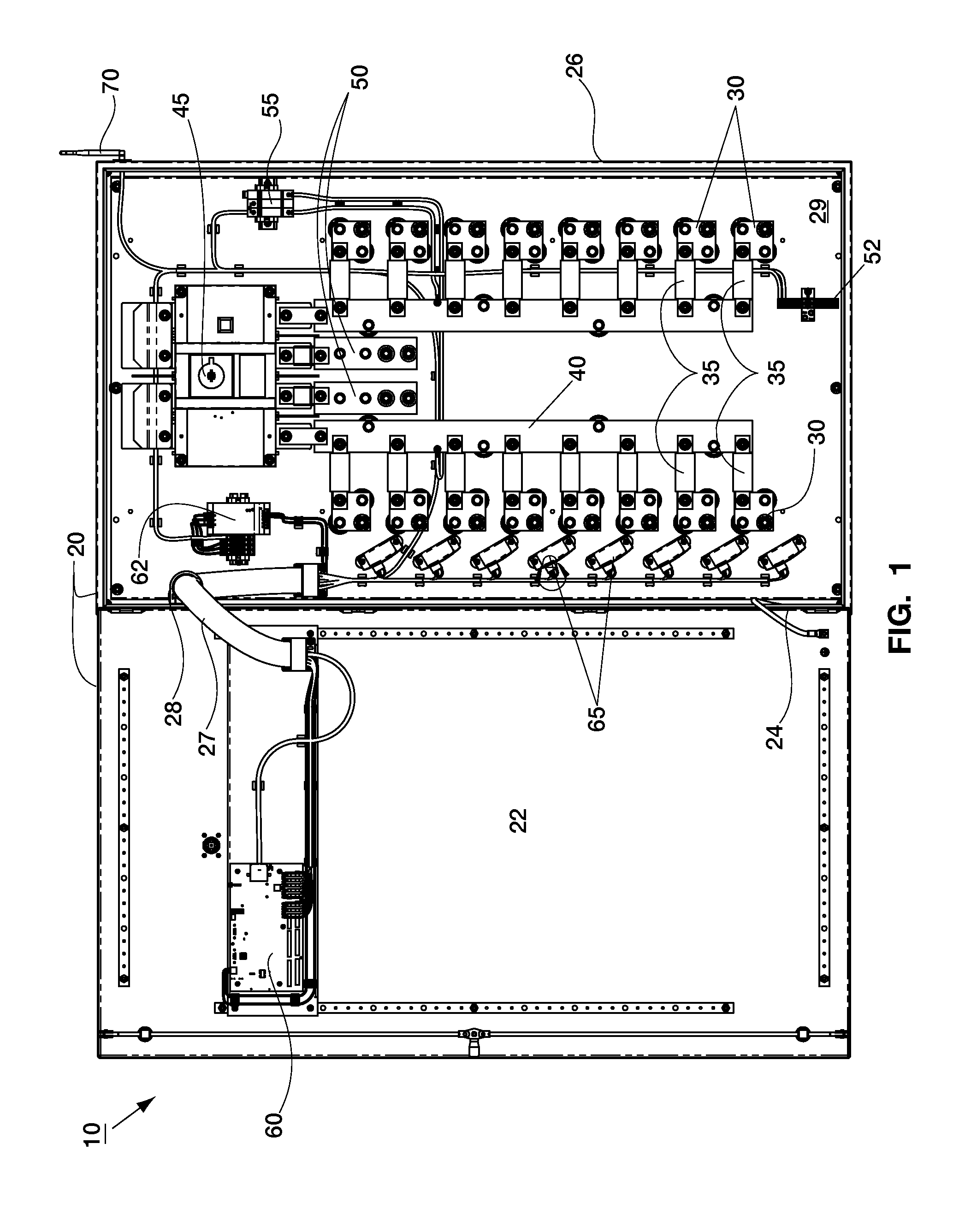
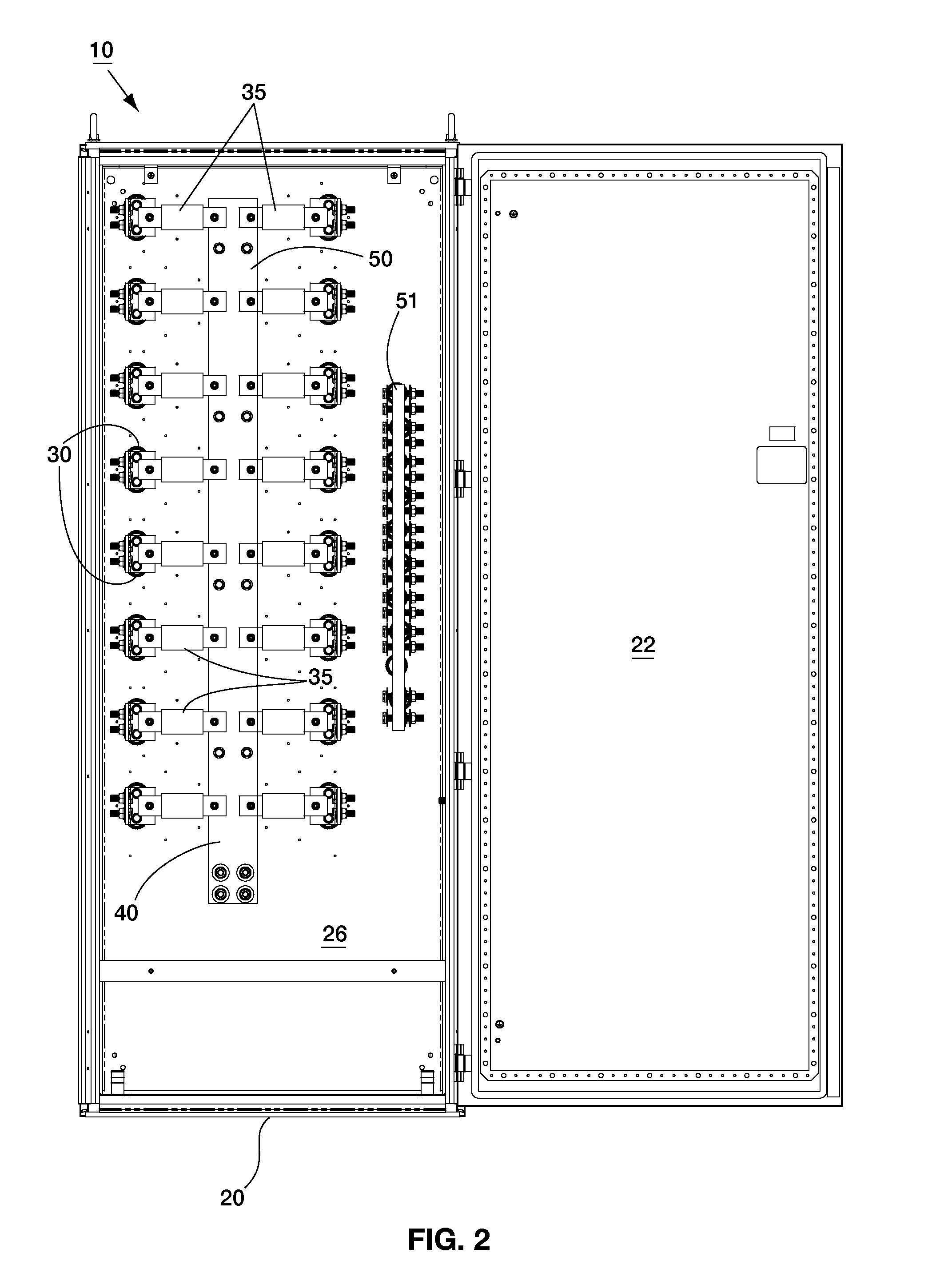
[0023]The following terms will apply:[0024]10—Recombiner box system;[0025]20—Cabinet;[0026]22—Door;[0027]24—Hinge;[0028]25—Safety shield;[0029]26—Housing;[0030]27—Conduit;[0031]28—Conduit clamp;[0032]29—Backpanel[0033]30—Input bus bar;[0034]35—Fuse;[0035]40—Recombining bus bar;[0036]45—Disconnect switch;[0037]50—Output bus bar;[0038]51—Unfused combining bus bar[0039]52—Earth Ground bus bar[0040]55—Surge protector;[0041]60—Control circuit board;[0042]62—Power supply;[0043]63—Power input;[0044]64—Current transducer input;[0045]65—Current transducer (“CT”);[0046]68—Output to antenna;[0047]70—Antenna;[0048]72—Receiver; and[0049]73—Processor.

[0050]As shown in FIG. 1, recombiner box system 10 is generally contained within cabinet 20 having housing 26 connected at hinge 24 to door 22. Housing 26 is preferably mounted to a substantially horizontal and stationary s...


PUM

PropertyMeasurementUnit
Electrically couplingaaaaaaaaaa
currentaaaaaaaaaa
power outputaaaaaaaaaa

Abstract

A master recombiner box system includes a plurality of input bus bars that receive power from a corresponding combiner box in a solar field. Each input bus bar is coupled with a current transducer, thereby measuring the current of the associated combiner box. Power feeding into the plurality of input bus bars is combined at a recombiner bus bar, which leads to an output bus bar, and ultimately to an external inverter. The current transducers are linked to a control circuit board which utilizes an antenna to send RF signals to a receiver. In this manner individual combiner boxes in a solar field can be monitored wirelessly.

Description

CROSS-REFERENCE TO RELATED APPLICATIONS[0001]This application claims priority from the United States provisional patent application entitled DISCONNECT CABINET AND RECOMBINER BOX WITH WIRELESS MONITORING CAPABILITY, which was filed on May 3, 2013, and assigned the Ser. No. 61 / 818,940.[0002]This application is being filed concurrently with a United States utility patent application entitled DISCONNECT CABINET WITH WIRELESS MONITORING CAPABILITY, which also claims priority from the provisional patent application entitled DISCONNECT CABINET AND RECOMBINER BOX WITH WIRELESS MONITORING CAPABILITY, which was filed on May 3, 2013, and assigned the Ser. No. 61 / 818,940. This co-pending application has a serial number of ______, and is hereby incorporated by reference in its entirety.BACKGROUND[0003]1. Field[0004]The present invention relates generally to components used in solar fields, and more particularly, to a master recombiner box that combines DC power from downstream combiner boxes, m...

Claims


Application Information

Patent Timeline
Patent Type & Authority Applications(United States)
IPC IPC(8): H05K5/00
CPCH05K5/0017H05K5/0004H01H47/002H01H71/1018H01H71/56Y10T29/49117
Inventor SOLON, DEAN
Owner SHOALS TECH GROUP
Learn More