Dynamic resource allocation method

a resource allocation and resource technology, applied in the field of resource allocation methods, can solve the problems of severe radio access network (ran) overload problem, large transmission load of highly dense devices supported by one cell, and congestion of signaling network

Inactive Publication Date: 2014-11-06
NAT TAIWAN UNIV OF SCI & TECH
View PDF6 Cites 18 Cited by
  • Summary
  • Abstract
  • Description
  • Claims
  • Application Information

AI Technical Summary

Benefits of technology

[0012]Accordingly, the present invention is directed to a dynamic resource allocation method, which could properly determine the allocated resources according to the number of contending devices.

Problems solved by technology

Regardless of whether cellular MTC is implemented over existing networks standards or over the upcoming LTE-A, it faces a severe Radio Access Network (RAN) overload problem.
Although MTC traffic is characterized with small data, the highly dense distribution of devices supported by one cell generates an enormous transmission load.
Congestion in the signaling network is caused by the large number of MTC devices trying almost simultaneously to access the network.
In a 3GPP system supporting MTC applications, this kind of overload situation of the network can be caused by a large number of metering devices becoming active almost simultaneously after a period of power outage.
If the MTC devices are notified using a one-by-one paging approach, the process would produce lots of signaling overhead, consume massive system resources and induce intolerable delay.
However, MTC devices seize their retransmission attempts upon success or the depletion of the allowable number of retransmission, so the number of contending devices changes from one RACH to another.
Accordingly, resources may be underutilized in the random access slots where the number of contending devices is very low.

Method used


Image

  • Dynamic resource allocation method
  • Dynamic resource allocation method
  • Dynamic resource allocation method

Examples


Embodiment Construction

[0025]Some embodiments of the present application will now be described more fully hereinafter with reference to the accompanying drawings, in which some, but not all embodiments of the application are shown. Indeed, various embodiments of the application may be embodied in many different forms and should not be construed as limited to the embodiments set forth herein; rather, these embodiments are provided so that this disclosure will satisfy applicable legal requirements. Like reference numerals refer to like elements throughout.

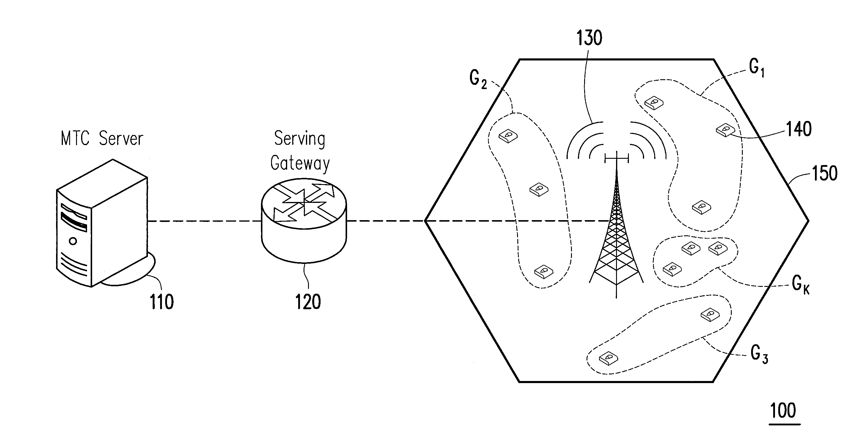
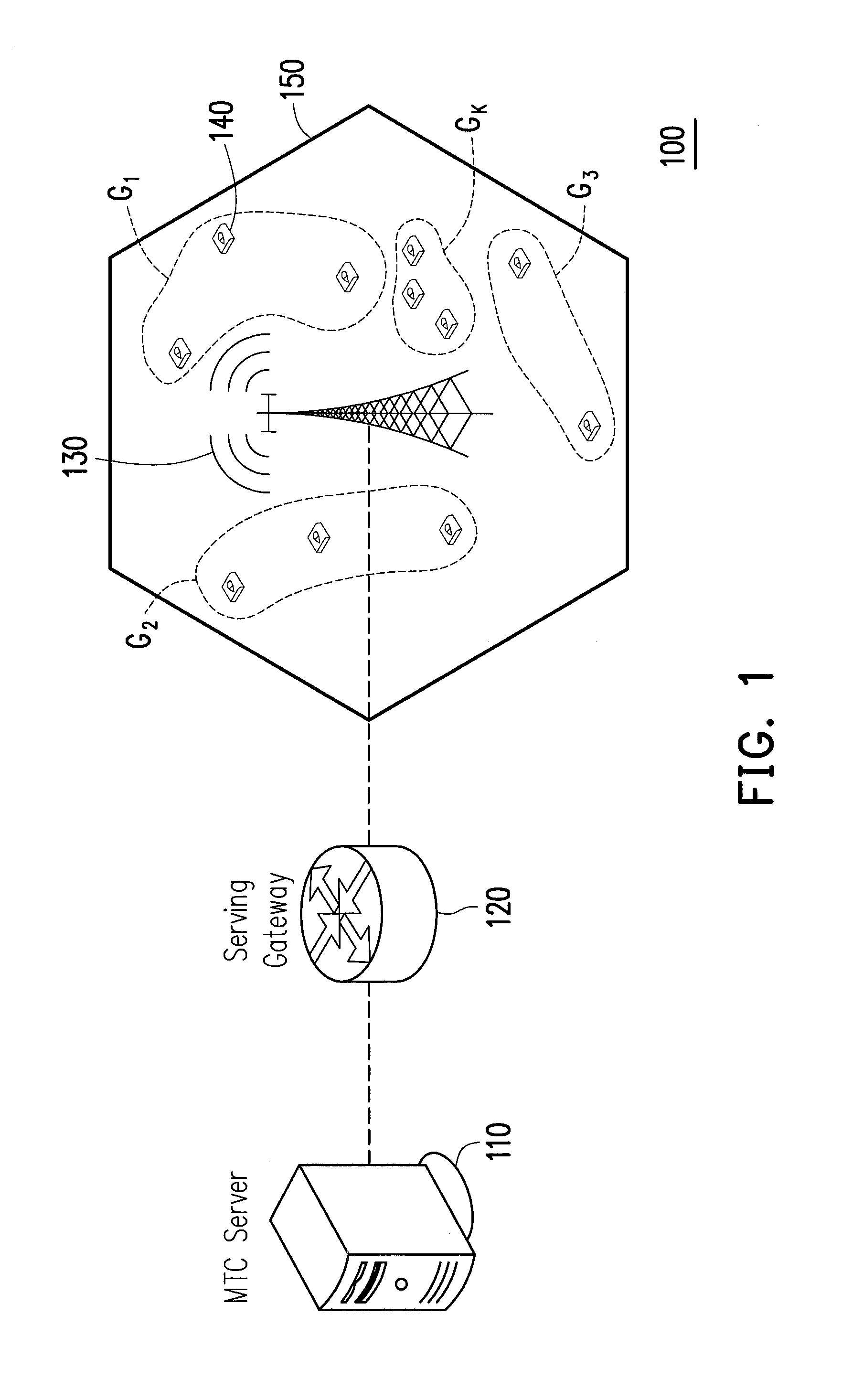
[0026]FIG. 1 is a schematic diagram illustrating an MTC system according to an exemplary embodiment of the present invention. In the present embodiment, the MTC system 100 includes an MTC server 110, a serving gateway 120, a base station 130 (i.e., an eNodeB) and a plurality of MTC devices 140. The MTC devices 140 may belong to a cell 150 managed by the base station 130. The MTC devices 140 may be partitioned into a plurality of communication groups G1-GK ...


PUM


Abstract

A dynamic resource allocation method is introduced herein. The method is adapted to a base station. The method includes the following steps. A number of contending devices in the random access slot is estimated. A reference value is calculated according to the number of the contending devices and a resource allocation parameter. A number of specific resources is calculated according to the number of the contending devices, a number of acknowledgeable machine-type communication devices of the base station at the random access slot and a preamble detection probability. A number of reserved random access opportunities is determined according to a maximum number of the random access opportunities, the number of the specific resources and the reference value. The resources are allocated to the at least one machine-type communication device according to the number of the reserved random access opportunities.

Description

CROSS-REFERENCE TO RELATED APPLICATION[0001]This application claims the priority benefit of Taiwan application serial no. 102115932, filed on May 3, 2013. The entirety of the above-mentioned patent application is hereby incorporated by reference herein and made a part of this specification.BACKGROUND[0002]1. Field of the Invention[0003]The invention relates to a resource allocation method, in particular, to a dynamic resource allocation method.[0004]2. Description of Related Art[0005]During the past decade, considerable research efforts have investigated the emergent topic of Internet of Things (IoT), where heterogeneous devices, spanning from smartphones and wireless sensors up to network-enabled physical objects can seamlessly interoperate in globally integrated communications platforms. IoT opens opportunities for much needed applications, some of which have already been implemented and others being under research.[0006]Machine-type communications (MTC) is the most solid enabler ...

Claims


Application Information

Patent Timeline
Patent Type & Authority Applications(United States)
IPC IPC(8): H04W72/04H04W4/00H04W4/70
CPCH04W72/0446H04W4/005H04W74/04H04W74/0833H04W4/70
Inventor CHENG, RAY-GUANGALTAEE, FIRAS MARDAN SHNAINWEI, CHIA-HUNG
Owner NAT TAIWAN UNIV OF SCI & TECH
Why Eureka
Try Eureka