Method for manufacturing impeller

Active Publication Date: 2014-11-06
HONDA MOTOR CO LTD
View PDF2 Cites 14 Cited by
  • Summary
  • Abstract
  • Description
  • Claims
  • Application Information

AI Technical Summary

Benefits of technology

[0007]According to an embodiment of the invention, a method for manufacturing impeller is provided in which an impeller can be molded by using a mold, thereby making it possible to fabricate t

Problems solved by technology

Thus, demanding high efficiency results in larger vanes.
When the multispindle machine tool is used, however, the working time becomes long to reduce the manufacturing efficiency, and moreover, the manufacturing cost is increased.
Because of this, it is n

Method used


Image

  • Method for manufacturing impeller
  • Method for manufacturing impeller
  • Method for manufacturing impeller

Examples


first embodiment

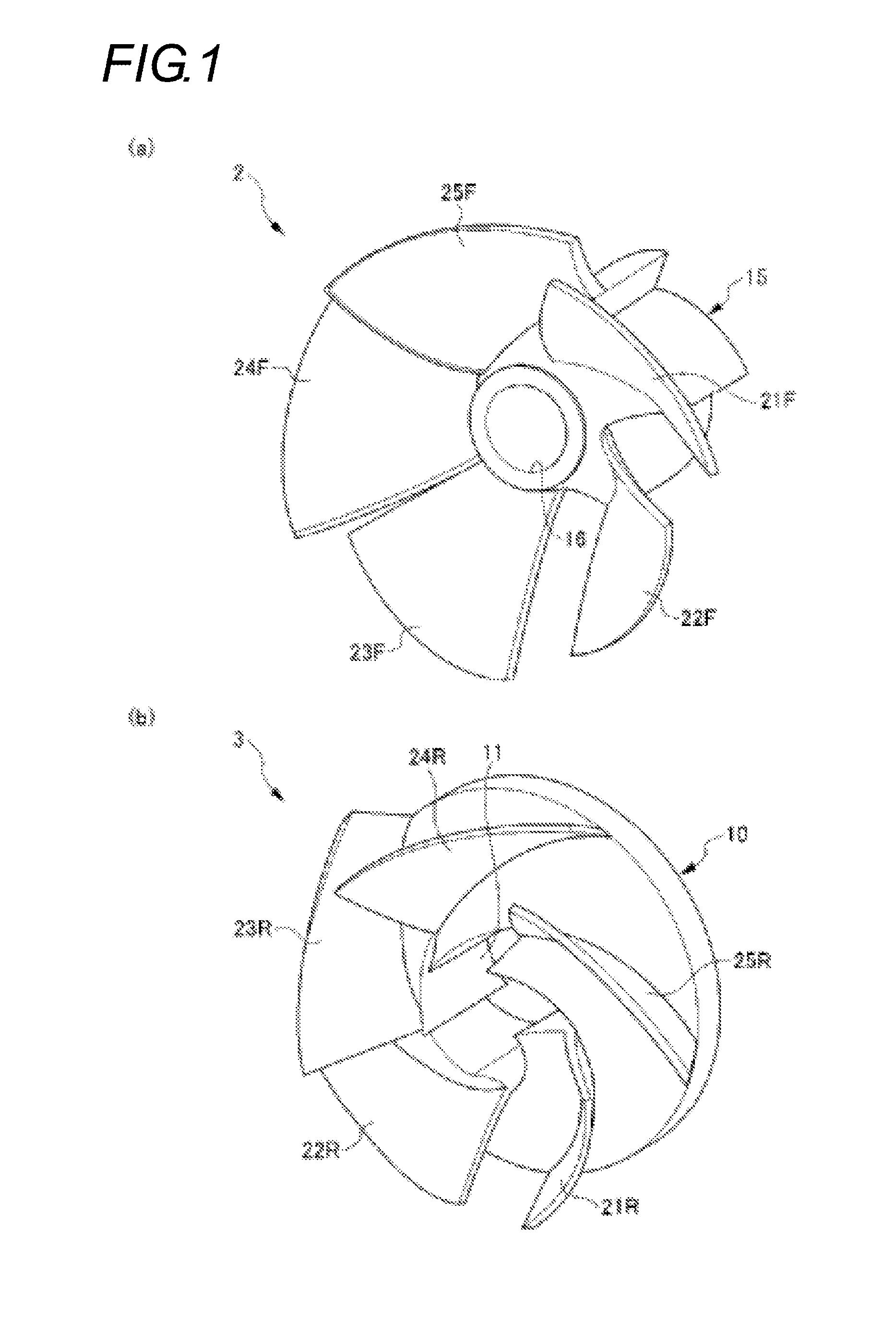
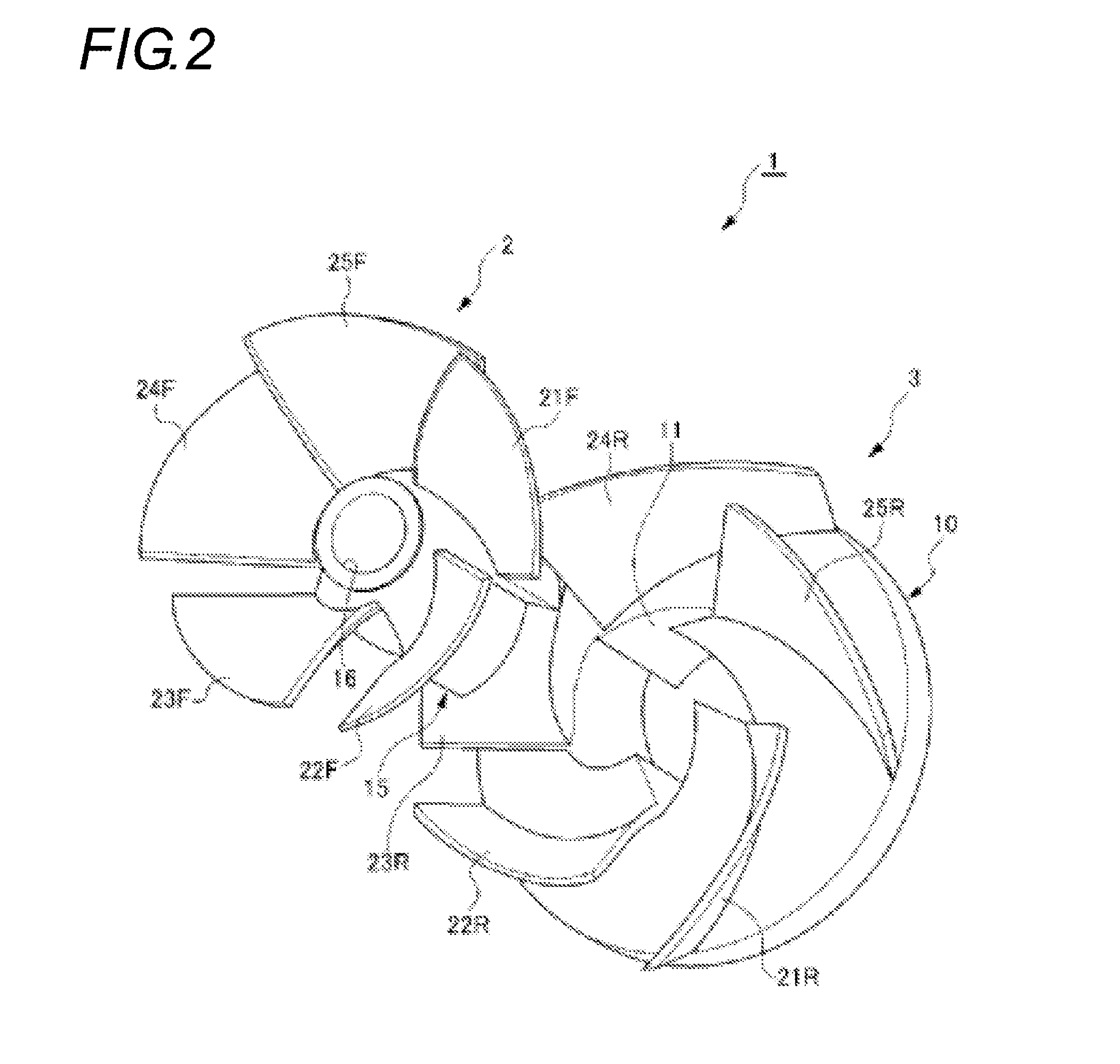
[0034]FIGS. 1(a) to 4 are drawings showing an impeller 1 according to a first embodiment and a first impeller part 2 and a second impeller part 3 which make up the impeller 1.

[0035]As shown in FIGS. 1(a) to 4, the impeller 1 includes a base 10 which is disposed at a rear surface, a shaft portion 15 which projects from a center portion of a front surface of the base 10 to the front, and a plurality of vanes 20 (specifically speaking, five vanes 21 to 25) which project sideways from an outer circumferential surface of the shaft portion 15. Hereinafter, reference numeral 20 will be used to describe the plurality of vanes indiscriminately, and reference numerals 21 to 25 will be used to describe the vanes discriminately.

[0036]As shown in FIG. 3, in the impeller 1, the plurality of vanes 20 are provided so as to overlap each other back and forth as viewed from the front in the direction of an axis thereof. Specifically speaking, when viewed from the front in the direction of the axis, ab...

second embodiment

[0062]FIGS. 10(a), 10(b) and 11 are drawings which show an impeller 5 according to a second embodiment and a first impeller part 6 and a second impeller part 7 which make up then impeller5. The impeller 5, the first impeller part 6 and the second impeller part 7 are almost similar to the impeller 1, the first impeller part 2 and the second impeller part 3 according to the first embodiment. Then, like reference numerals will be given to like portions to those of the first embodiment, and a detailed illustration and description thereof will be omitted here.

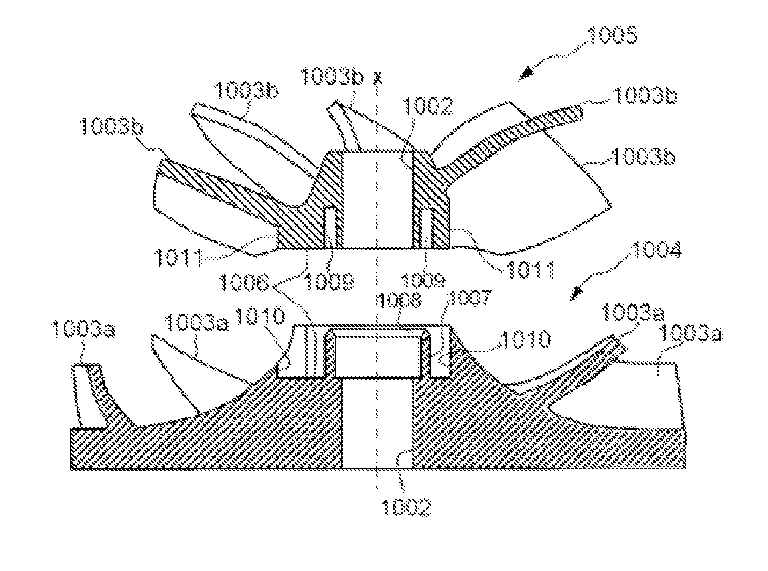
[0063]A base 10 of the second impeller part 7 has a welding margin 12 formed at a rearmost portion of an accommodating hole 11 which is welded when a shaft portion 15 of the first impeller part 6 is accommodated. The length of the shaft portion 15 of the first impeller part 6 is shortened by such an extent that the welding margin 12 is provided at the rearmost portion of the accommodating hole 11 of the second impeller part 7.

[0064]...

third embodiment

[0066]FIGS. 12(a) to 19(b) are drawings which show a second impeller part 107 which makes up an impeller (its illustration being omitted) according to a third embodiment and a mold 160 which molds the second impeller part 107. This impeller includes a first impeller part (its illustration being omitted) and the second impeller part 107, and they are similar, for example, to the impeller 5, the first impeller part 6 and the second impeller part 7 according to the second embodiment, respectively. Because of this, reference numerals which result from adding 100 to the reference numerals used in the second embodiment will be given to like portions to those of the second embodiment, and a repeated description thereof will be omitted here.

[0067]When compared with the second impeller part 7 according to the second embodiment shown in FIGS. 10(b) and 11, the second impeller part 107 shown in FIG. 12(a) is different in the following points. In the second impeller part 107, there are provided...


PUM

PropertyMeasurementUnit
Energyaaaaaaaaaa

Abstract

An impeller in which a plurality of vanes are provided so as to overlap each other back and forth as viewed in the direction of axis has a first impeller part on a front side and a second impeller part on a rear side. A method for manufacturing impeller includes a step of molding a first impeller part, a step of molding a second impeller part and a step of combining together the first impeller part and the second impeller part.

Description

CROSS-REFERENCE TO RELATED APPLICATIONS[0001]The present application claims the benefit of priority of Japanese Patent Applications No. 2011-228086 filed on Oct. 17, 2011, No. 2012-083871 filed on Apr. 2, 2012, and No. 2012-154832 filed on Jul. 10, 2012, which is incorporated herein by reference.TECHNICAL FIELD [0002]The present invention relates to a method for manufacturing impeller.BACKGROUND ART [0003]An impeller is used in, for example, a compressor or a pump. This type of impeller is required to be small in size and highly efficient and is desired to be designed into a shape which satisfies the requirements. To impart kinetic energy from the impeller to a fluid with good efficiency, it is advantageous that the contact area of vanes of the impeller with the fluid becomes larger. Thus, demanding high efficiency results in larger vanes. Further, attempting to reduce the size of the impeller while satisfying the requirements by changing continuously the shape of the impeller from ...

Claims


Application Information

Patent Timeline
IPC IPC(8): F04D29/28F04D17/10B29C37/00F04D29/62
CPCF04D29/284F04D29/624B29L2031/08B29C37/0021F04D17/10F04D29/285F04D29/023F04D29/026F04D29/2222B29L2031/7496B29C65/08B29C66/124B29C66/30223B29C66/54B29C66/73921B29C66/8322F05D2300/43F05D2230/23
Inventor ISHIKAWA, HIROSHITSURUGAI, YOSHINORISAITO, YASUHISA
Owner HONDA MOTOR CO LTD
Why Eureka
Try Eureka