Rear casing, rotor blade with rear casing, and a wind turbine that comprises such a rotor blade

Active Publication Date: 2014-11-06
WOBBEN PROPERTIES GMBH
View PDF10 Cites 5 Cited by
  • Summary
  • Abstract
  • Description
  • Claims
  • Application Information

AI Technical Summary

Benefits of technology

The present invention provides a rear box section, rotor blade and wind power installation. By designing the rear box section into separate foot and head segments, it becomes easier and cheaper to manufacture, ship and assemble. The use of bonding agents, such as epoxy resin, makes the glueing process more efficient and cost-effective in comparison to screwing or riveting. The resulting join is stronger and more durable, while the need for reinforcements is minimized.

Problems solved by technology

That gives rise to additional logistical and time constraints.

Method used


Image

  • Rear casing, rotor blade with rear casing, and a wind turbine that comprises such a rotor blade
  • Rear casing, rotor blade with rear casing, and a wind turbine that comprises such a rotor blade
  • Rear casing, rotor blade with rear casing, and a wind turbine that comprises such a rotor blade

Examples


first embodiment

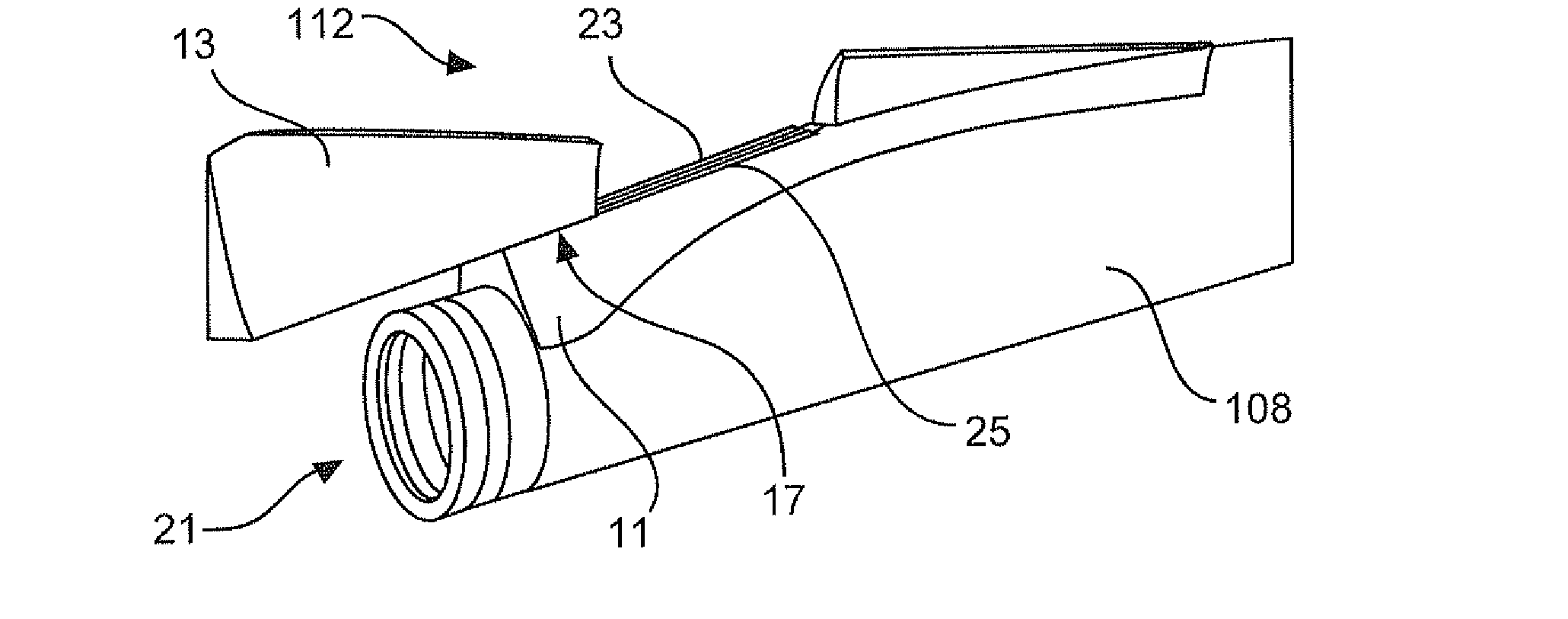
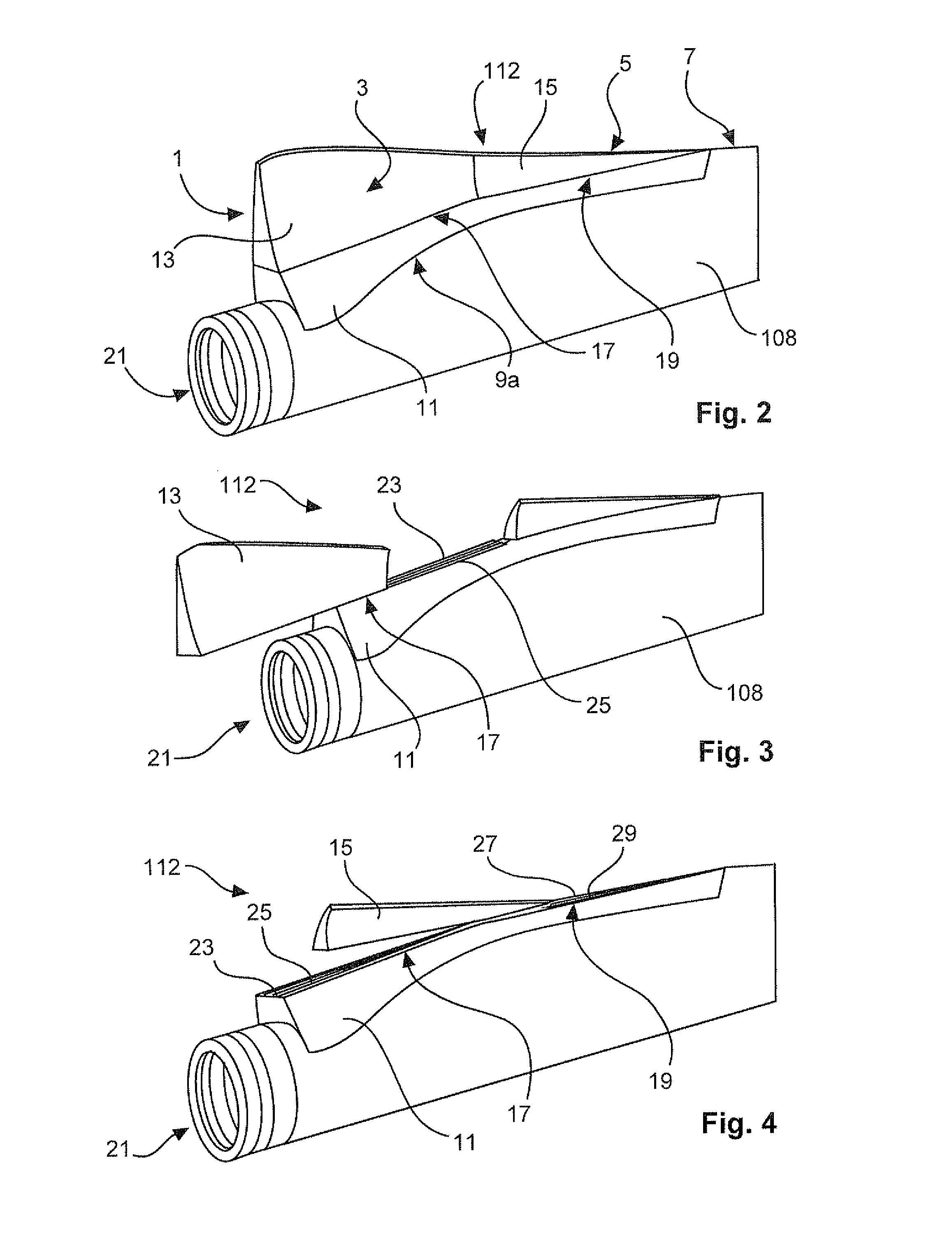
[0058]A rotor blade with a rear box section according to the invention is shown in FIGS. 2 to 5. The rotor blade shown in FIGS. 2 to 5 has the rear box section 112 in a region adjoining the rotor blade root 21. The rear box section 112 has a suction-side surface 1, a pressure-side surface 3 and a trailing edge 5 separating the pressure-side and the suction-side surfaces 1, 3. Arranged opposite the trailing edge 5 is the connecting side of the rear box section 112 in relation to the rotor blade 108. Extending at the connecting side are a first edge 9a and a second edge 9b (see FIG. 5) which delimit the surfaces 1,3 of the rear box section 112 and are adapted to the curvature of the rotor blade 108. In the mounted condition the trailing edge 5 of the rear box section 112 is aligned with the trailing edge 7 of the rotor blade 108 and blends fluidly into same.

[0059]The rear box section 112 has a foot segment 11 having the connecting side. The rear box section 112 is sub-divided and in t...

second embodiment

[0063]In FIGS. 7 and 9 the rear box section 112 in accordance with the second embodiment, is shown as being supported on a support frame structure 201. The support frame structure 201 is omitted in FIG. 8, as also in FIG. 6, which serves for illustrative purposes.

[0064]FIG. 7 shows how the head segments 13, 15 and 35 are respectively brought out of engagement with the rails respectively associated therewith on the foot segment 11 (see also FIG. 9). In regard to the first head segment, the rails 41, 43 are indicated by way of example.

[0065]A similar fitting and removal position is also shown in FIG. 8 where however a better view on to the underside of the leg 39 of the head segment 13 is possible, and the rails 41, 43 can be better seen.

[0066]As can also be seen from FIGS. 6 and 7 the head segment 13 has a step 45 on the pressure and suction sides of the surfaces of the rear box section 112. At the same location (with respect to the mounted condition of the head segment 13 on the foo...


PUM


Abstract

The invention concerns a rear box section for a rotor blade, in particular of a wind power installation, comprising a pressure-side surface, a suction-side surface, a trailing edge separating the pressure-side and suction-side surfaces, and a connecting side which is opposite to the trailing edge and which is adapted for mounting to a corresponding connecting surface of the rotor blade. The invention concerns in particular a rear box section which is sub-divided into a foot segment having the connecting side and one or more head segments which have the trailing edge and which can be coupled to the foot segment. The invention also concerns a rotor blade for a wind power installation, and a wind power installation.

Description

BACKGROUND[0001]1. Technical Field[0002]The present invention concerns a rear box section for a rotor blade, in particular of a wind power installation, comprising a pressure-side surface, a suction-side surface, a trailing edge separating the pressure-side and suction-side surfaces, and a connecting side which is opposite to the trailing edge and which is adapted for mounting to a corresponding connecting surface of the rotor blade.[0003]The invention further concerns a rotor blade for a wind power installation, comprising a supporting portion, a rotor blade root embraced by the supporting portion for mounting to a rotor of a wind power installation, a pressure-side blade surface, a suction-side blade surface and a trailing edge separating the pressure-side and the suction-side surfaces. The invention also concerns a wind power installation.[0004]2. Description of the Related Art[0005]Wind power installations are becoming increasingly used because of the increased endeavors in the ...

Claims


Application Information

Patent Timeline
IPC IPC(8): F03D1/06
CPCF03D1/0658F03D1/0683F03D1/0641F03D1/0675F05B2230/60F05B2240/30F05B2240/302F05B2260/30F03D13/40Y02E10/72Y02P70/50
Inventor HOFFMANN, ALEXANDERKANNENBERG, JOHANNESBAKER, LAURENCESPIETH, FALK
Owner WOBBEN PROPERTIES GMBH
Why Eureka
Try Eureka