Interbody distractor

a distractor and body technology, applied in the field of implanters, can solve the problems of poor placement and subsidence of implants, difficult to properly seat intervertebral body devices, and chronic lower back pain, and achieve the effect of correcting spinal deformity and facilitating the insertion of associated implants

Active Publication Date: 2014-11-06
CUSTOM SPINE INC
View PDF1 Cites 4 Cited by
  • Summary
  • Abstract
  • Description
  • Claims
  • Application Information

AI Technical Summary

Benefits of technology

[0022]The expansion head may be adjusted to at least one of the first height, the second height, the third height, or the fourth height to enable at least one of (i) a distraction of disc space and associated ligamentous tissues, (ii) a correction of spinal deformity, and (iii) an easier insertion of the associated implant in the vertebral body.

Problems solved by technology

Intervertebral disc degeneration often leads to chronic lower back pain that occurs with aging.
Due to variable spinal anatomy, it is often difficult to seat intervertebral body devices properly to support the best quality bone during surgery.
Thus, poor placement and subsidence of implants can occur leading to implant failure and diseases of the spine such as kyphosis (e.g., a curvature of the upper spine which can be either the result of bad posture or a structural anomaly in the spine), and lordosis (e.g., an inward curvature of a portion of the vertebral column).
This may also be due to abnormal loading patterns on the disc or inappropriate means of distracting the disc space.
Passing various size footprints (e.g., use of multiple instruments such as standard footprints and height trials, multiple trial instruments, distractor and trial inserters, medical cage inserters, etc.) by sensitive vascular and neural anatomy can also cause damage to the structures leading to secondary morbidities.
Further, they are also static in size, and only distract the disc space if an oversize trial is chosen.
The combination distractor and trial inserters and cage implant inserters in general are typically large and bulky, and they only allow insertion of standard trial pre-assembled to the same instrument.
Such combination distractor and trial inserters require multiple assemblies and multiple passes of various trials if the proper size is not initially chosen since they cannot measure angle of deformity at the same time.

Method used


Image

  • Interbody distractor
  • Interbody distractor
  • Interbody distractor

Examples


Embodiment Construction

[0042]The embodiments herein and the various features and advantageous details thereof are explained more fully with reference to the non-limiting embodiments that are illustrated in the accompanying drawings and detailed in the following description. Descriptions of well-known components and processing techniques are omitted so as to not unnecessarily obscure the embodiments herein. The examples used herein are intended merely to facilitate an understanding of ways in which the embodiments herein may be practiced and to further enable those of skill in the art to practice the embodiments herein. Accordingly, the examples should not be construed as limiting the scope of the embodiments herein.

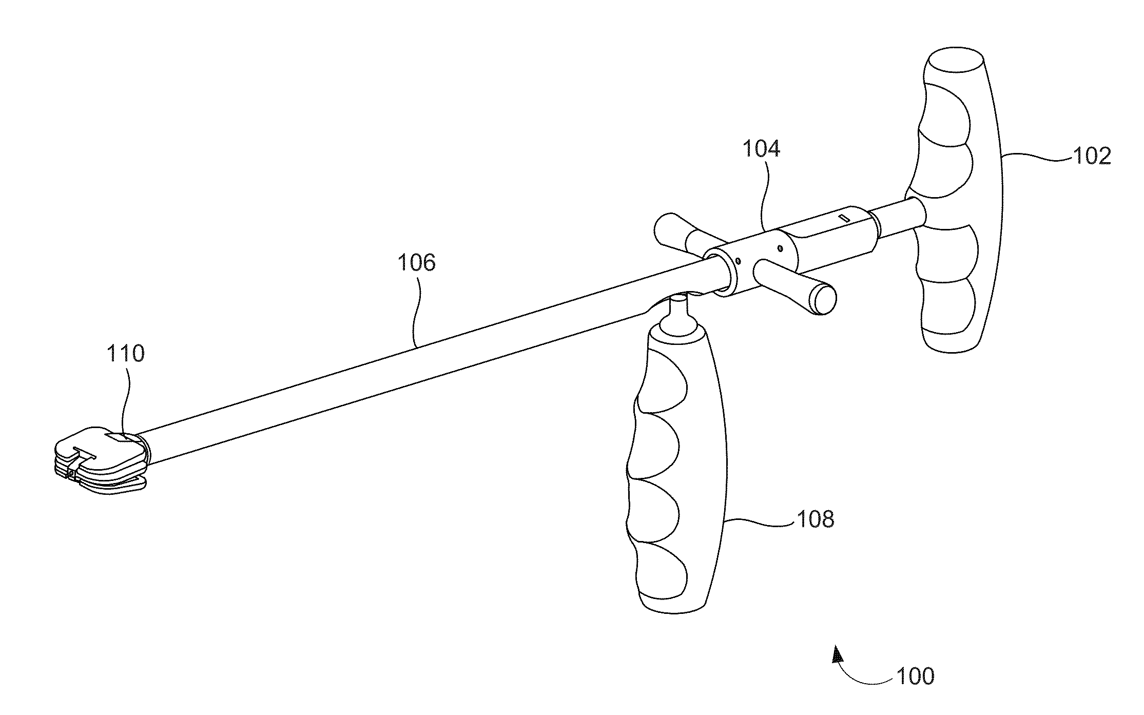
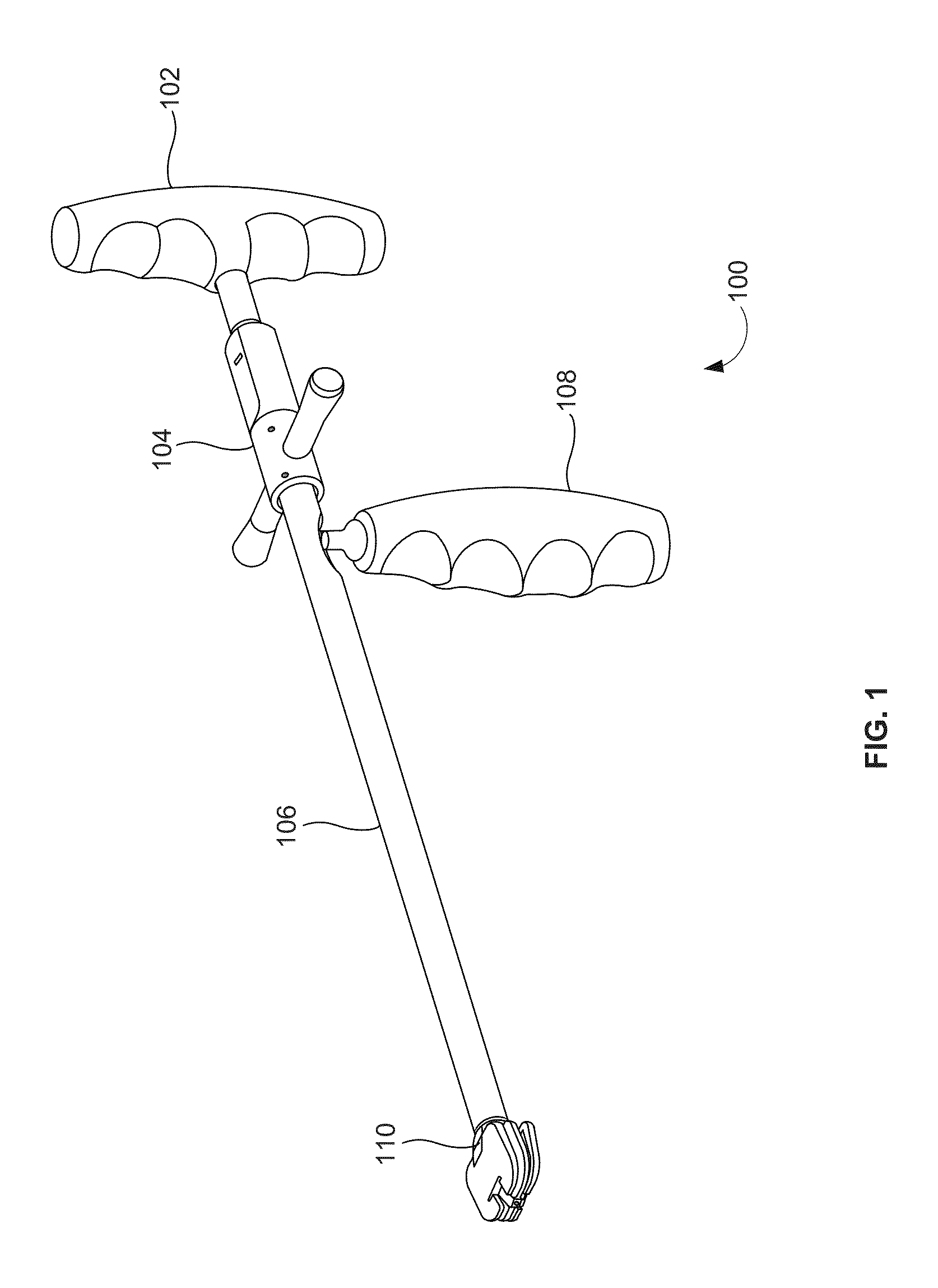
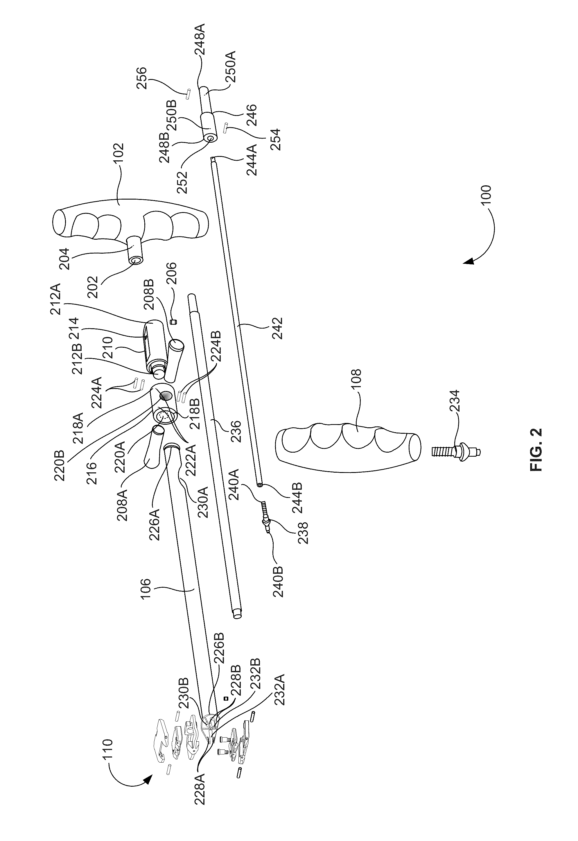
[0043]As mentioned, there remains a need for a distractor trial assembly that allows a user to distract the disc space to various heights and measure an angle of lordosis / kyphosis for proper sizing and choice of matching interbody implants. The embodiments herein achieve this by providing an in...


PUM


Abstract

An interbody distractor and geometry trial instrument to measure a height and an angle for an associated implant includes a height handle and an expansion head coupled to the height handle that is adapted to be positioned in a vertebral body. A wedge sleeve is coupled to the expansion head, to control an angle of a first surface plate and a second surface plate of the expansion head when the wedge sleeve interacts with the expansion head. A wedge sleeve knob is adapted to drive the wedge sleeve linearly towards the vertebral body when the wedge sleeve knob is actuated. A height of the expansion head and an angle of the first and the second surface plate are measured to determine the height and the angle of the associated implant when the height handle and the wedge sleeve knob are actuated.

Description

BACKGROUND[0001]1. Technical Field[0002]The embodiments herein generally relate to medical devices, and, more particularly, to inserter devices used during orthopedic surgeries.[0003]2. Description of the Related Art[0004]Intervertebral disc degeneration often leads to chronic lower back pain that occurs with aging. Due to variable spinal anatomy, it is often difficult to seat intervertebral body devices properly to support the best quality bone during surgery. Thus, poor placement and subsidence of implants can occur leading to implant failure and diseases of the spine such as kyphosis (e.g., a curvature of the upper spine which can be either the result of bad posture or a structural anomaly in the spine), and lordosis (e.g., an inward curvature of a portion of the vertebral column). This may also be due to abnormal loading patterns on the disc or inappropriate means of distracting the disc space. Passing various size footprints (e.g., use of multiple instruments such as standard f...

Claims


Application Information

Patent Timeline
Patent Type & Authority Applications(United States)
IPC IPC(8): A61B17/02A61B19/00
CPCA61B17/025A61B19/46A61B2019/461A61B2019/467A61B2017/0256A61F2/4684A61F2/4611A61F2002/30266A61F2002/30471A61F2002/30556A61F2002/4627A61B2090/067A61B2090/061A61F2/4603
Inventor MARKWORTH, AARONSICHLER, KEVIN
Owner CUSTOM SPINE INC
Why Eureka
Try Eureka