
Minimally invasive spinal stabilization system

a spinal stabilization and minimally invasive technology, applied in the field of minimally invasive spinal stabilization system, can solve the problem of still challenging to provide the minimally invasive spinal stabilization that is required

Inactive Publication Date: 2014-11-06
IND TECH RES INST
View PDF6 Cites 4 Cited by
  • Summary
  • Abstract
  • Description
  • Claims
  • Application Information

AI Technical Summary

Benefits of technology

The minimally invasive spinal fixation assembly described in this patent is designed to be implanted through small incisions in the spine, reducing patient risks and recovery time. It includes a U-shaped pedicle screw stabilizer and a pedicle screw breaking device that allows for separation of the screw head from the rod. The device also includes a method of threading a suture through a series of implanted pedicle screws, and using the suture to link them using a pedicle rod. The invention allows for a larger region of the spine to be fixed than some known minimally invasive spinal fixation methods.

Problems solved by technology

Although a discectomy is frequently performed using minimally invasive devices and procedures, it is still challenging to provide the minimally invasive spine stabilization that is required following this and other spinal procedures.

Method used


Image

  • Minimally invasive spinal stabilization system
  • Minimally invasive spinal stabilization system
  • Minimally invasive spinal stabilization system

Examples


Embodiment Construction

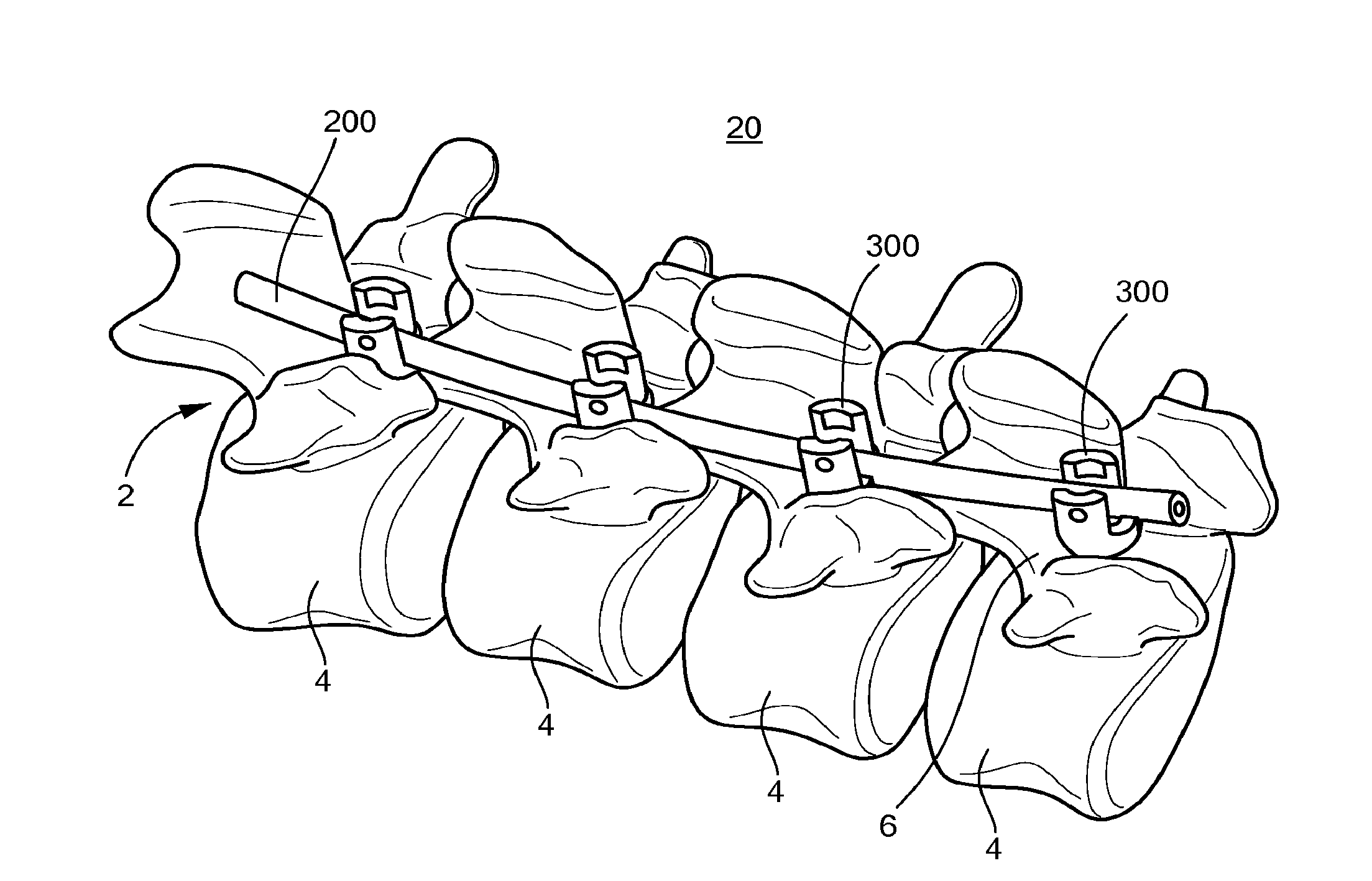
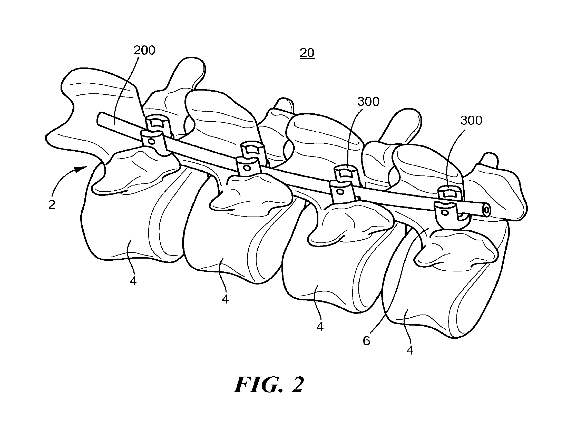
[0050]Referring to FIG. 2, a minimally invasive spinal fixation system 20 used to stabilize a region of the spine 2 includes a fixation rod 200 of sufficient length to extend across the vertebrae 4 to be stabilized, pedicle screws 300 for anchoring the fixation rod 200 to each corresponding vertebra 4, and a fastener 500 on each pedicle screw 300 to secure the pedicle rod 200 to the pedicle screw 300. Each pedicle screw 300 is implanted in the pedicle 6 of the corresponding vertebra 4 through a small skin incision having a length generally corresponding to a cross sectional dimension of the pedicle screw 300. In the illustrated embodiment, for example, the incision has a length of 1 cm or less, and the rod 200 is assembled with the pedicle screws 300 through a separate skin incision of 1 cm or less, as discussed further below.

[0051]Referring to FIG. 3, the fixation rod 200 is a structure that is configured to engage a suture, where a suture is defined herein as an elongated strand o...


PUM


Abstract

A spinal fixation assembly including a pedicle rod and pedicle screws which secure the pedicle rod to the spine. Each pedicle screw includes a head configured to receive a portion of the pedicle rod, and a threaded portion extending from a first end of the head and configured to engage a vertebra. The pedicle rod is secured to the head by a fastener. The head includes a breakaway region that defines a location in which at least a first portion of the head can be easily separated from the remainder of the head upon application of sufficient force to the first portion.

Description

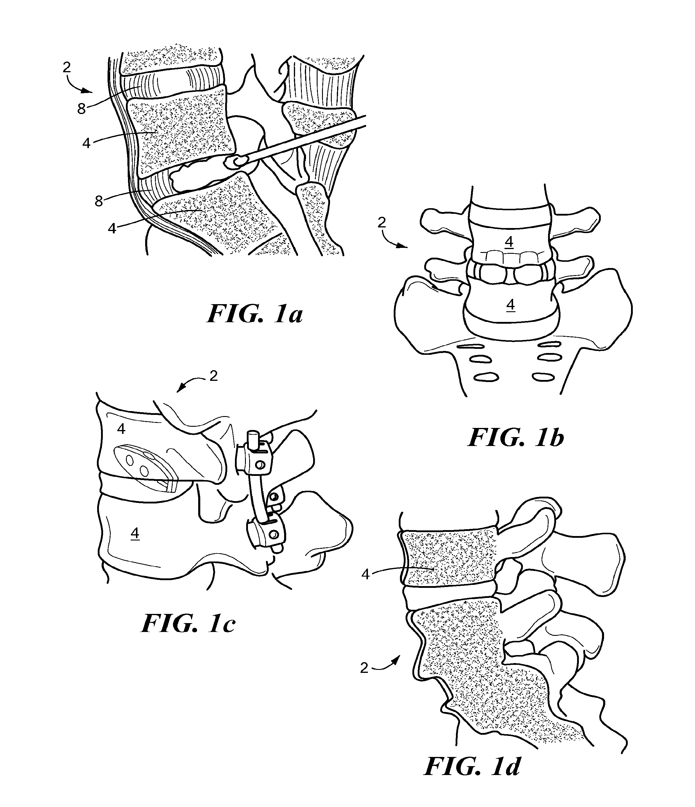
CROSS-REFERENCE TO RELATED APPLICATIONS[0001]This application is a continuation of U.S. application Ser. No. 13 / 161,686, filed on Jun. 16, 2011. The content of the prior application is hereby incorporated by reference in its entirety.BACKGROUND OF THE INVENTION[0002]Each year 13 million people see a doctor for chronic back pain, which is estimated to cause 2.4 million Americans to be chronically disabled. About 25 percent of people who have back pain have a herniated disk. In the US, about 450 cases of herniated disk per 100,000 require surgery such as a discectomy.[0003]Referring to FIG. 1, a discectomy (FIG. 1(a)) is performed when the intervertebral disc 8 has herniated or torn and has not responded to a more conservative treatment. When a surgeon performs a discectomy, it is usually performed through an incision in the patient's back at a location corresponding to the problem area of the spine 2. Muscles and ligaments are moved aside to expose the offending disc 8. The surgeon t...

Claims


Application Information

Patent Timeline
Patent Type & Authority Applications(United States)
IPC IPC(8): A61B17/70
CPCA61B17/7002A61B17/1671A61B17/1757A61B17/7032A61B17/7085A61B17/7089A61B17/7091A61B17/8863A61B2090/037
Inventor TSUANG, YANG-HWEILIAO, CHUN-JENLIANG, HUANG-CHIENHAN, SHIH-JUITSUANG, FON-YIHCHIANG, CHANG-JUNG
Owner IND TECH RES INST
Learn More