
Method and control device for controlling foreseeable haptically perceivable signals in an acceleration pedal of a motor vehicle

a technology of haptic acceleration and control device, which is applied in the direction of electric/magnetic computing, instruments, analogue processes for specific applications, etc., can solve the problems of disproportionate increase in fuel consumption, and achieve the effect of keeping the energy consumption of the actuator of the accelerator pedal low

Inactive Publication Date: 2014-11-06
ROBERT BOSCH GMBH
View PDF2 Cites 2 Cited by
  • Summary
  • Abstract
  • Description
  • Claims
  • Application Information

AI Technical Summary

Benefits of technology

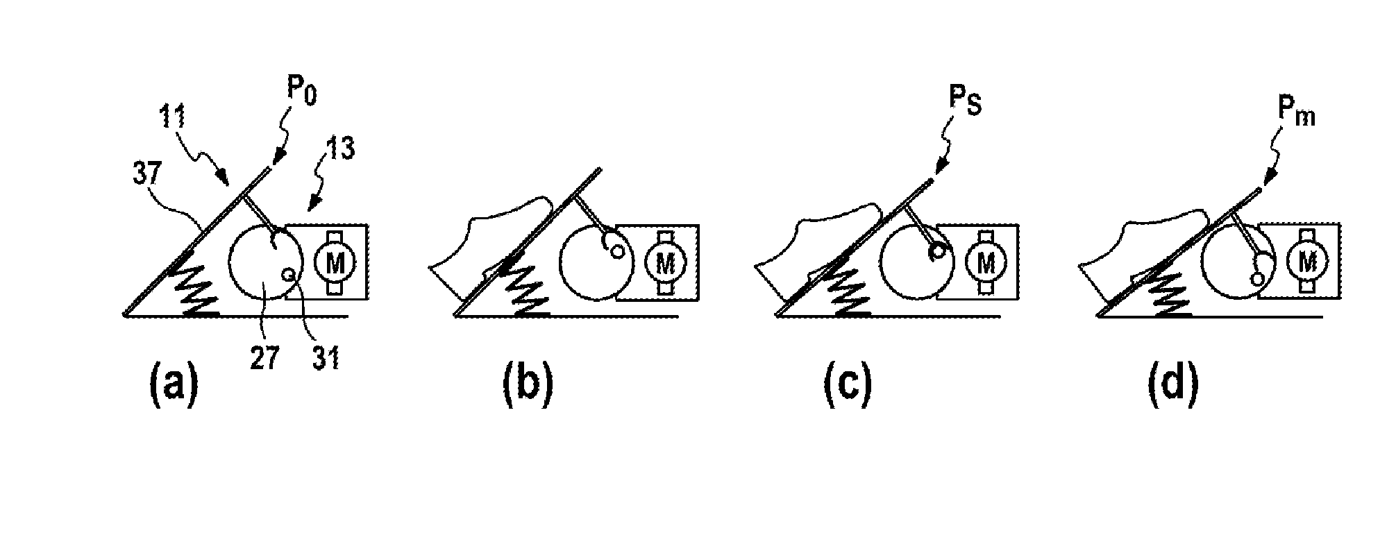
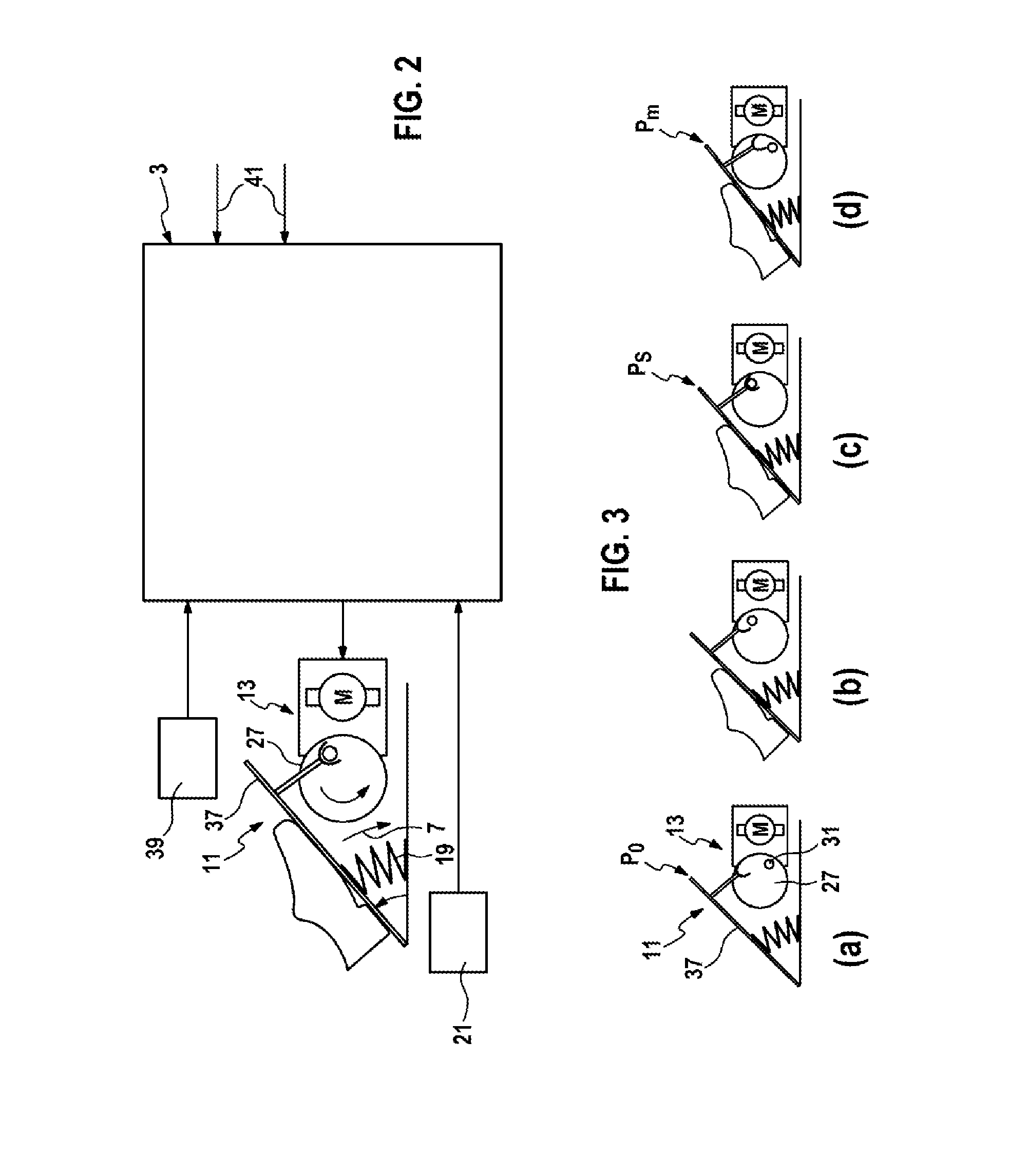
The present invention provides a method for actuating a haptic accelerator pedal in a motor vehicle in a way that generates quickly and with low energy consumption. The actuator is positioned in an intermediate position between rest and the intended haptic signal position. This allows for a predictable haptic signal to be generated with minimal movement of the actuator and without adding unnecessary energy consumption. The energy requirement for the actuator can be kept low by adjusting its position based on external factors that may affect the desired haptic signal position. This method reduces the need for continuous movement of the actuator and can save energy compared to other position control methods.

Problems solved by technology

For example, starting from a certain accelerator pedal position the actuator can selectively counteract further depression of the accelerator pedal in order in this way to signal to a driver, for example, that stronger depression of the accelerator pedal would lead to a disproportionate increase in the consumption of fuel.

Method used


Image

  • Method and control device for controlling foreseeable haptically perceivable signals in an acceleration pedal of a motor vehicle
  • Method and control device for controlling foreseeable haptically perceivable signals in an acceleration pedal of a motor vehicle
  • Method and control device for controlling foreseeable haptically perceivable signals in an acceleration pedal of a motor vehicle

Examples


Embodiment Construction

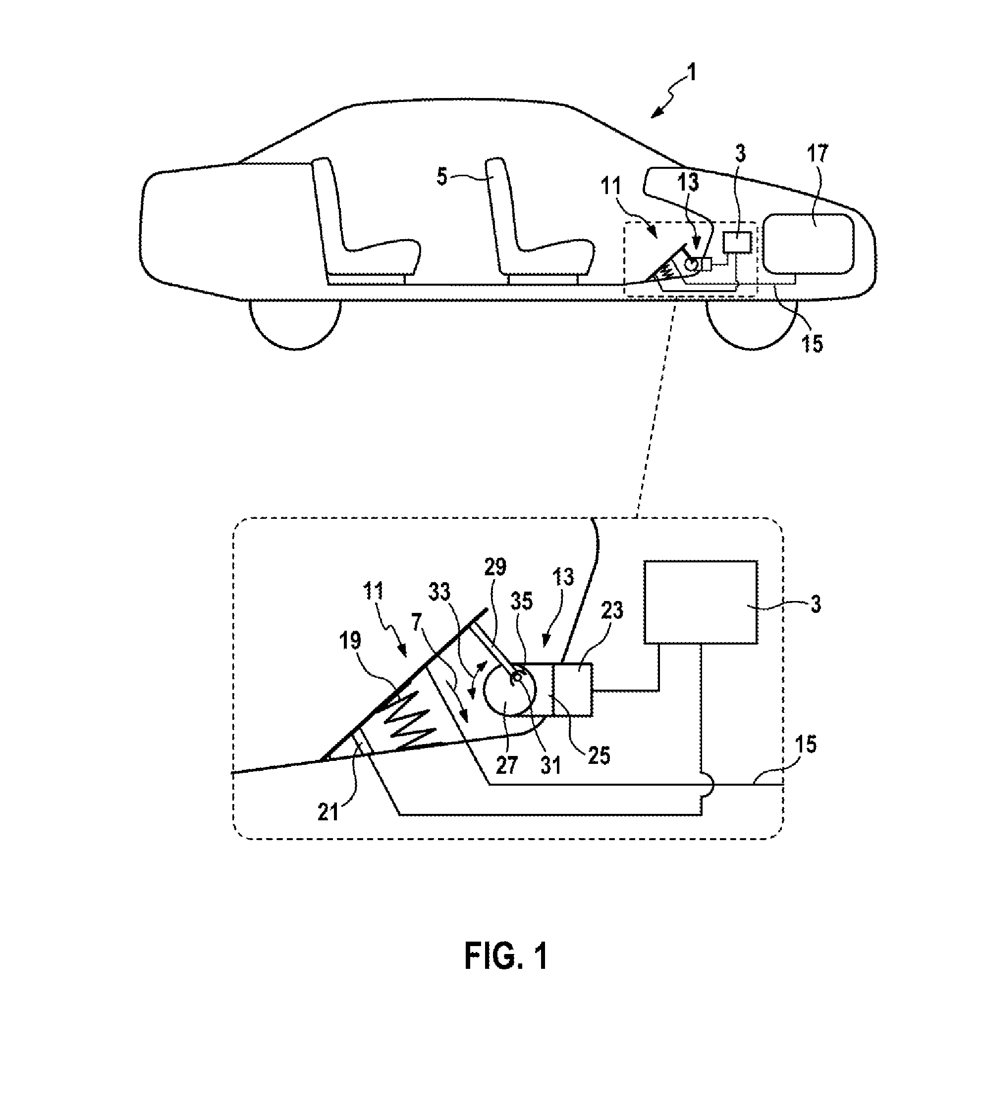
[0033]FIG. 1 shows a sectional view of a vehicle 1 with a haptic accelerator pedal 11. By depressing the accelerator pedal it is possible for a driver sitting on a seat 5 to cause an engine 17 of the vehicle 1 to accelerate the vehicle via a Bowden cable 15 or a line (not illustrated) which is connected to an engine control device. To do this, the driver must depress the accelerator pedal 11 in the direction of the arrow 7, as a result of which the accelerator pedal 11 can be moved from a position of rest along a movement range to a position of maximum actuation. A position sensor 21 can determine here the current position of the accelerator pedal 11. A spring 19 prestresses the accelerator pedal toward the position of rest counter to the actuation direction 7.

[0034]The accelerator pedal 11 is configured as a haptic accelerator pedal. For this purpose, the accelerator pedal 11 has an actuator 13 which can be used to move the accelerator pedal 11 in a desired direction counter to the...


PUM


Abstract

A method and a control device for controlling a haptic acceleration pedal in a motor vehicle includes determining a foreseeable signal position in which a haptically perceivable signal is foreseeably to be generated by the acceleration pedal at a future time. The signal position is configured to be located between a rest position and a maximally actuated position within the shifting range of the pedal. While the pedal is located in a current position between the rest position and the foreseeable position, an actuator that is configured to generate a haptically perceivable signal on the acceleration pedal is arranged in such manner that the actuator is in operational connection with the acceleration pedal when the acceleration pedal has reached the foreseeable position. The configuration results in a prompt generation of a haptically perceivable signal and a reduced energy consumption for the actuator.

Description

FIELD OF THE INVENTION[0001]The present invention relates to a method and to a control device for controlling a haptic accelerator pedal in a motor vehicle. The invention also relates to a computer program product which is intended to execute the method according to the invention when said computer program product is executed on a programmable control device, and to a computer-readable medium on which such a computer program product is stored.PRIOR ART[0002]In modern motor vehicles, the driver is assisted in driving the vehicle by a large amount of information which is made available. For example, it may be helpful to signal feedback about specific driving states to the driver or to signal requests to the driver to carry out certain measures in order to be able to increase the safety when driving or the comfort of the driver or in order to be able to save fuel. This feedback can be made available in different ways, such as for example visually or audibly.[0003]In modern motor vehicl...

Claims


Application Information

Patent Timeline
Patent Type & Authority Applications(United States)
IPC IPC(8): B60K26/02
CPCB60K26/021B60K2026/022Y02T10/84
Inventor SIEBER, UDODEISSLER, MARKUSHENNING, DANIEL
Owner ROBERT BOSCH GMBH
Learn More