
Displacement sensor

a technology of displacement sensor and displacement sensor, which is applied in the direction of generator/motor, instrument, force/torque/work measurement apparatus, etc., can solve the problem of not being able to precisely detect (measure) the displacement proportional to the amount of charges generated

Active Publication Date: 2014-11-13
MURATA MFG CO LTD
View PDF2 Cites 17 Cited by
  • Summary
  • Abstract
  • Description
  • Claims
  • Application Information

AI Technical Summary

Benefits of technology

The present invention provides a displacement sensor that can accurately detect the amount of displacement given by an operator. This is achieved by setting the impedance of the resistors in a specific way, which results in a stable temporal change in voltage in response to changes in displacement. The sensor is also designed to suppress the influence of changes in charges generated by the piezoelectric element, and to achieve high sensitivity and translucency. Overall, the invention enables accurate measurement of displacement and provides a more reliable and efficient solution for detecting operator actions.

Problems solved by technology

According to the conventional configuration, it is not easy to precisely detect (measure) the amount of displacement proportional to charges generated by a piezoelectric sensor due to characteristics of the piezoelectric sensor.

Method used


Image

  • Displacement sensor
  • Displacement sensor
  • Displacement sensor

Examples


first embodiment

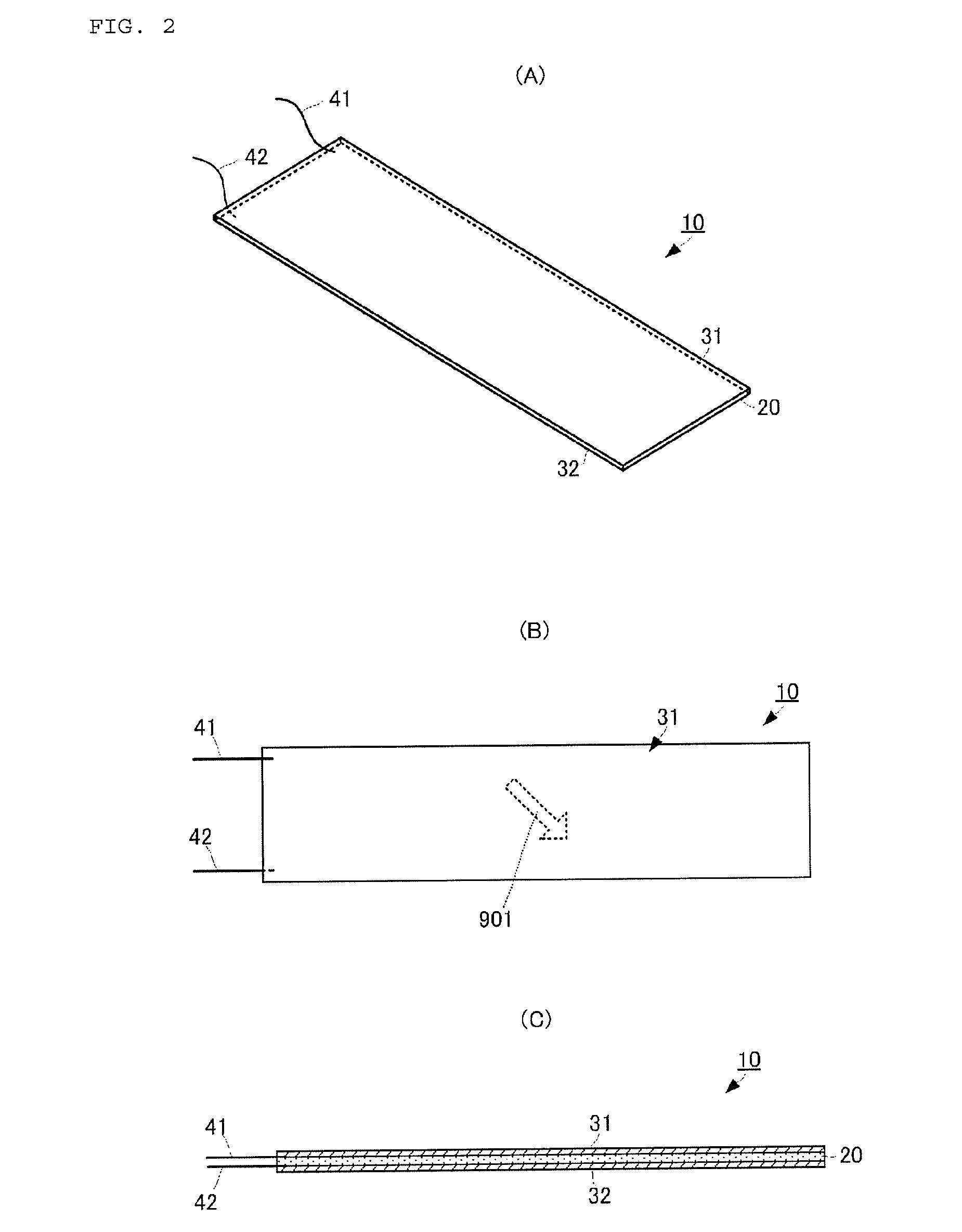
[0050]When the flat surface of the piezoelectric element 10 is pushed, a charge is generated and a potential difference is produced between the first detection electrode 31 and the second detection electrode 32. FIGS. 3(A) and 3(B) each are a view for explaining a function of generating a charge when the piezoelectric element 10 is pushed according to the present invention. FIG. 3(A) illustrates a state where the amount of pushing (pressing force) is not applied, and FIG. 3(B) illustrates a state where the amount of pushing (pressing force) by the finger is applied.

[0051]As illustrated in FIG. 3(A), the piezoelectric element 10 is attached to one principal surface of a flat elastic body 50 such that respective flat surfaces are closely attached. The elastic body 50 is formed using glass, acryl or polycarbonate. The material of the elastic body 50 is not limited to the materials disclosed herein, and an adequate material only needs to be selected according to use conditions. Further,...

third embodiment

[0095]The reset function equipped pressing amount calculating unit 202A of the computing unit 122A calculates the amount of pressing using a flowchart illustrated in FIG. 12. FIG. 12 is a flowchart illustrating a pressing amount calculating flow executed by the reset function equipped pressing amount calculating unit 202A according to the

[0096]The reset function equipped pressing amount calculating unit 202A (simply referred to as the “calculating unit 202A” below) measures an integration value Zout outputted from the integrating unit 201, and sequentially compares the integration values Zout (S101). The calculating unit 202A continues measuring and comparing the integration values Zout until the calculating unit 202A detects that the integration value Zout fluctuates up and down (S102: NO). That is, as illustrated in FIG. 6, until the integration value Zout rises, takes a fixed value and then lowers, the calculating unit 202A continues measuring and comparing the integration values...


PUM


Abstract

There is provided a displacement sensor which can precisely detect the amount of displacement given by an operator. A touch sensor which is a type of the displacement sensor has a piezoelectric element, a voltage converting unit and a detecting unit. The piezoelectric element instantaneously generates a voltage proportional to a pressing force (the amount of pressing). The voltage converting unit converts the voltage generated by the piezoelectric element, into a voltage proportional to a transition determined based on a predetermined time constant determined by an impedance of a resistor of the voltage converting unit and capacitances of a capacitor and the piezoelectric element, and a pressing force. The detecting unit integrates output voltages of the voltage converting unit, and calculates the pressing force (the amount of pressing) based on an integration value.

Description

CROSS REFERENCE TO RELATED APPLICATIONS[0001]The present application is a continuation of PCT / JP2013 / 051530 filed Jan. 25, 2013, which claims priority to Japanese Patent Application No. 2012-012839, filed Jan. 25, 2012, the entire contents of each of which are incorporated herein by reference.FIELD OF THE INVENTION[0002]The present invention relates to a displacement sensor which detects the amount of displacement when an operator operates (bends, twists or pushes) a main body.BACKGROUND OF THE INVENTION[0003]Conventionally, various types of displacement sensors which detect the amounts of displacement when an operator operates a main body have been devised. Operations performed on a main body include bending the main body, twisting the main body and pushing a predetermined surface (a touch surface) of the main body. Various types of touch sensors which detect the amounts of pushing upon touching when an operator touches a flat operation surface by the finger have been devised as to...

Claims


Application Information

Patent Timeline
IPC IPC(8): G06F3/038G06F3/0338G01L1/16
CPCG06F3/038G01L1/16G06F3/0338G01B7/003H10N30/802H10N30/304
Inventor ISHII, TORUYAMAMOTO, YASUSHIYONEMITSU, TSUTOMU
Owner MURATA MFG CO LTD
Learn More