
Light system for building structures

a technology for building structures and light systems, applied in lighting and heating equipment, instruments, manufacturing tools, etc., can solve the problems of easy damage to displays, poor durability, and difficult to integrate the known kind of displays with the building structure in a discreet manner, and achieve the effects of low power, energy saving, and economical operation

Active Publication Date: 2014-11-13
DUPONT LIGHTSTONE APS
View PDF5 Cites 16 Cited by
  • Summary
  • Abstract
  • Description
  • Claims
  • Application Information

AI Technical Summary

Benefits of technology

The present invention relates to light sources that can be used in building blocks. These light sources can be LEDs that are connected directly to the building block or embedded within it. The light sources can be powered by traditional AC electrical sources, batteries, or other powering sources like solar, wind, or chemically or organically derived energy. Using an LED light source, the system requires low power and is cost-effective to operate. The technical effect of the invention is to provide efficient and economical light sources for building blocks.

Problems solved by technology

The known displays are therefore placed directly on the building surface and when used outside sensitive to the weather conditions, because their electronic circuits for instance can be damaged by rain, snow or wind and further dust and sand could also damage the displays.
Another issue is the fact that it is very difficult to integrate the known kind of displays with the building structure in a discreet way such that the display and building structure would appear as one unit.
LED screens are today build into walls but are not considered as a natural part of the building when turned on and not even when they are turned off.
In some applications it is further desired to integrate / place large displays on surfaces such as floors, pavements, roads and other surfaces in floor / street level but this is not possible with the existing technologies due to the fact that the existing displays easily could be damaged when positioned in these kinds of surfaces
This type of system use a soft, plastic-like material placed over the light elements through which the light can emanate, but this approach suffers from the same limitations of poor durability.
All of the present known attempts to provide for a self-illuminating fabricated solid present problems that include solids that require chambers, grooves, channels, pockets or panels of significant size for housing a light bulb or other light source from which light is emitted through a soft material located on the top surface of the solid.
Additionally, none of these devices provide for an illuminating fabricated solid object, such as a paving block or stepping stone that has the strength, versatility and functionality of a concrete block or stepping stone, that provides for a lighted surface that includes various colors, patterns, or designs of light which may cover either part or the entire surface of the block or stone, where the light source means may be directly connected to the solid, or, alternatively, where the light source may be indirectly connected to the solid, by way of a fiber optic cable, for example, to provide for a plurality of solid objects to receive light from just one or a few light source means, and where the light source means, the color of the light, and the design that is displayed on a visible surface can be changed or replaced easily and rapidly without having to replace the entire object.

Method used


Image

  • Light system for building structures
  • Light system for building structures
  • Light system for building structures

Examples


Embodiment Construction

[0023]The following description of the preferred embodiments of the invention is not intended to limit the invention to these preferred embodiments, but rather to enable any person skilled in the art to make and use this invention.

[0024]The lighting system of the present invention may be used as a sign for pedestrians, vehicles, or bicycles in concrete barriers or abutments, may be used as a display in or on building walls, floors, or ceilings, or may be used in any other suitable environment.

[0025]Though rods of limited opacity may be employed in certain instances, typically a preferred rod will be made of any transparent or otherwise translucent material. Preferably, the material has percentage transmission of at least about 50%; more preferably at least about 75%; and most preferably at least about 90%. Preferably, the material is at least partially amorphous or more preferably is substantially entirely amorphous glass or a plastic such as acrylates, methacrylates, polycarbonates...


PUM

PropertyMeasurementUnit
transparentaaaaaaaaaa
translucentaaaaaaaaaa
colorsaaaaaaaaaa

Abstract

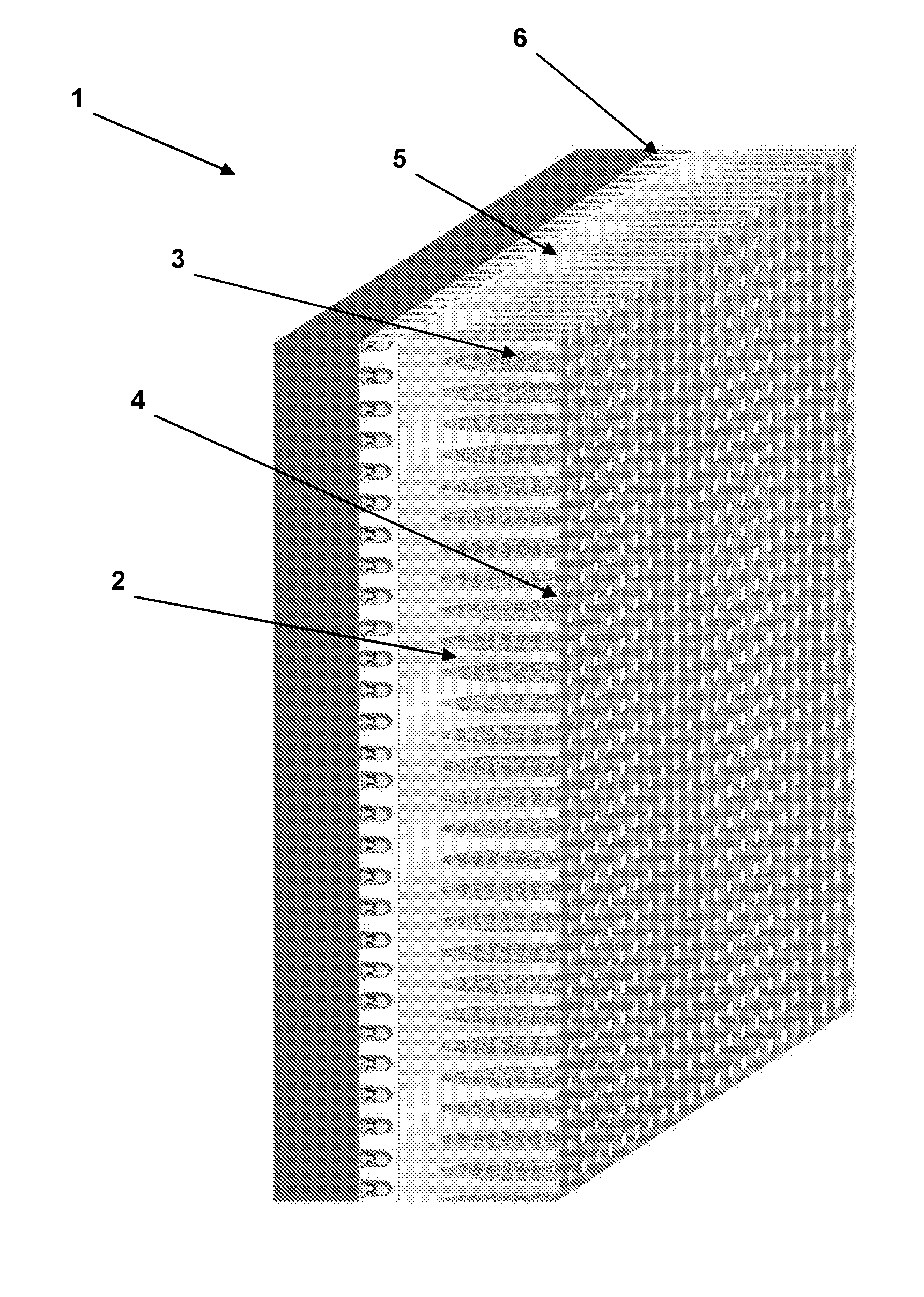
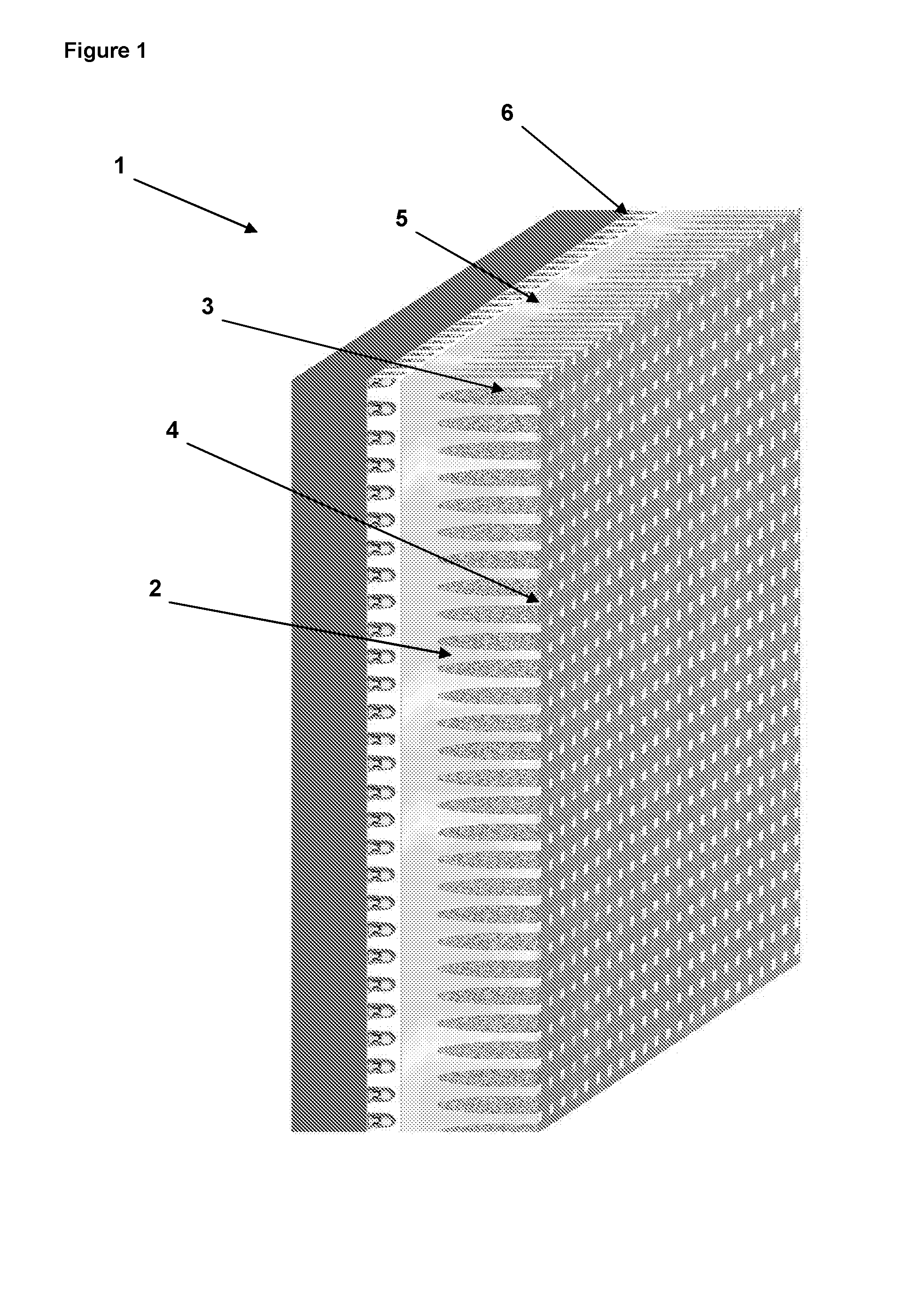
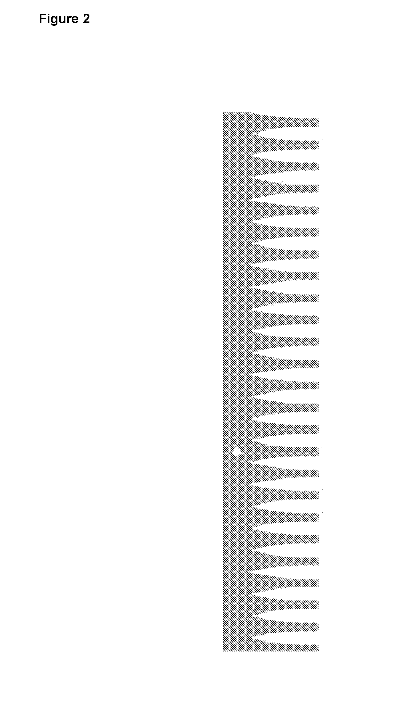
There is provided embedded light guiding parts that allow for light, signals or live images to appear on its surface. Specifically there is provided a light system having an array of rods made in a hard transparent or translucent polymer material embedded in a building material. The tapered rods are held together by a back-bone that connects the bases of the tapered rods to achieve an evenly distributed array of tapered rods, preferably having the same orientation, wherein the rods are adapted to receive a light input at the base ends and to transmit the light output at the front ends of the rods.

Description

FIELD OF THE INVENTION[0001]The present invention relates generally to embedded light guiding parts that allow for light, signals or live images to appear on its surface. Specifically the present invention relates to a transparent array of rods, especially tapered rods, made in a hard transparent or translucent polymer material, which is embedded in a building material.BACKGROUND OF THE INVENTION[0002]It is very often desired to place displays, such as advertisement, news, TV, video displays on building surfaces such that the display could be seen by many people. Such displays are typically constructed as a large electronic TV screen comprising a number of light emitting pixels, such as LCD or LED screens, or constructed by projecting the image onto the surface of the building. The known displays are therefore placed directly on the building surface and when used outside sensitive to the weather conditions, because their electronic circuits for instance can be damaged by rain, snow ...

Claims


Application Information

Patent Timeline
Patent Type & Authority Applications(United States)
IPC IPC(8): F21V33/00G09G3/32
CPCF21V33/006G09G3/32G02B6/08Y10T29/49002B28B23/0037
Inventor DUPONT SKOVSBY, CHRISTOFFER
Owner DUPONT LIGHTSTONE APS
Learn More