Scan lens, interferometric measuring device using same

a technology of interferometry and scanning lens, which is applied in the field of scanning lens, can solve the problems of interfering and interfering with each other, and achieve the effect of narrowing the size of the interferometry measuring device and reducing the optical path during interferometry measuremen

Active Publication Date: 2014-11-13
NAT TAIWAN UNIV
View PDF7 Cites 0 Cited by
  • Summary
  • Abstract
  • Description
  • Claims
  • Application Information

AI Technical Summary

Benefits of technology

[0007]It is, therefore, the main objective of the present invention to provide a scan lens, which comprises a lens set, a beam splitter, and a reflector, wherein the reflector is set between the lens set and the beam splitter. A light beam that passes through the lens set is projected onto the beam splitter to split the light beam into a first light beam and a second light beam. The first light beam that passes through the beam splitter is projected onto the test object. The second light beam that is reflected by the beam splitter is projected onto the reflector. Thus, the first light beam that is reflected or scattered by the test object and the second light beam that is reflected by the reflector will interfere with each other at the beam splitter. By means of the use of the scan lens, the optical path during interferometric measurement is shortened, facilitating narrowing the size of the interferometric measuring device.

Problems solved by technology

Thus, the first light beam that is reflected or scattered by the test object and the second light beam that is reflected by the reflector will interfere with each other at the beam splitter.
Thus, the first light beam that is reflected or scattered by the test object and the second light beam that is reflected by the transmission device will interfere with each other at the beam splitter.

Method used


Image

  • Scan lens, interferometric measuring device using same
  • Scan lens, interferometric measuring device using same
  • Scan lens, interferometric measuring device using same

Examples


first embodiment

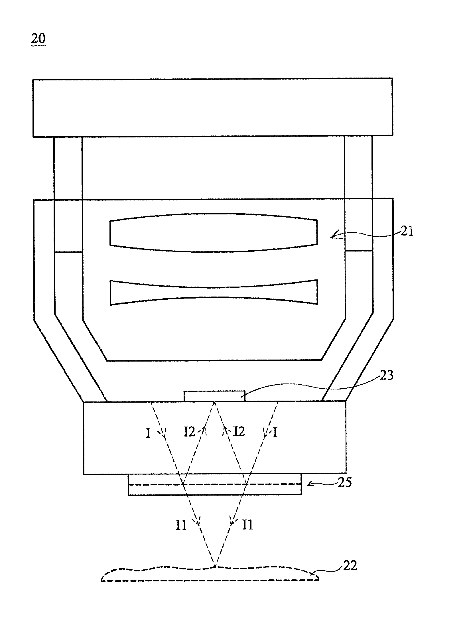
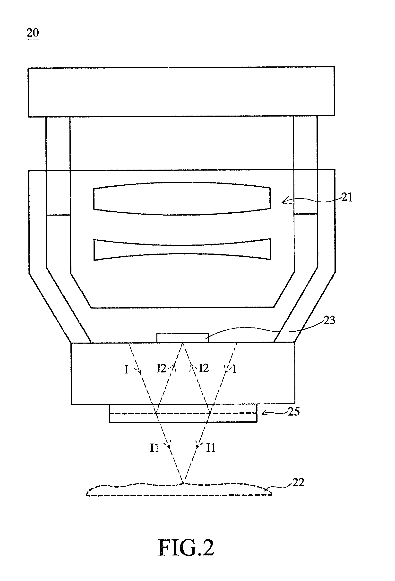
[0040]Please refer to FIG. 2, a scan lens in accordance with the present invention is shown. As illustrated, the scan lens 20 comprises a lens set 21, a reflector 23, and a beam splitter 25, wherein the reflector 23 is set between the lens set 21 and the beam splitter 25.

[0041]During application, the applied light beam I passes through the lens set 21 where the lens set 21 changes the focus position of the light beam I. After passed through the lens set 21, the light beam I falls upon the beam splitter 25 for splitting. At this time, a part of the light beam I passes through the beam splitter 25, and another part of the light beam I is reflected by the beam splitter 25. In one embodiment, the part of the light beam I that passes through the beam splitter 25 is defined as a first light beam I1, and the part of the light beam I that reflected by the beam splitter 25 is defined as a second light beam I2.

[0042]The reflector 23 is disposed between the lens set 21 and the beam splitter 25...

second embodiment

[0045]Referring to FIG. 3, a scan lens in accordance with the present invention is shown. As illustrated, the scan lens 30 comprises a lens set 21, a light transmission device 37, a reflector 33, and a beam splitter 25, wherein the light transmission device 37 is set between the lens set 21 and the beam splitter 25, and the reflector 33 is located on the light transmission device 37.

[0046]In this embodiment, the reflector 33 can be a thin film, for example, metal thin film selected from the group of aluminum, silver, aluminum-silver alloys and gold, and covered on the surface of the light transmission device 37. In one embodiment, the light transmission device 37 defines a first surface 371 and a second surface 373. The first surface 371 faces toward the lens set 21. The second surface 373 faces toward the beam splitter 25. The reflector 33 is mounted at the second surface 373 of the light transmission device 37.

[0047]The reflector 33 is disposed between the lens set 21 and the beam...

third embodiment

[0052]Referring to FIG. 4, a scan lens in accordance with the present invention is shown. As illustrated, the scan lens 40 comprises a lens set 21, a light transmission device 47, a light shade 49, and a beam splitter 25, wherein the light transmission device 47 is set between the lens set 21 and the beam splitter 25, and the light shade 49 is located on the light transmission device 47.

[0053]The light transmission device 47 comprises a first surface 471 and a second surface 473, wherein the first surface 471 faces toward the lens set 21, and the second surface 473 faces toward the beam splitter 25. The light shade 49 is arranged on the first surface 471 of the light transmission device 47.

[0054]In actual application, the applied light beam I passes through the lens set 21 and the light transmission device 47 to fall upon the beam splitter 25. Because the light shade 49 is disposed between the lens set21 and the beam splitter 25, the light shade 47 will block a part of the light bea...


PUM


Abstract

A scan lens and an interferometric measuring device using the scan lens are disclosed. The scan lens includes a lens set, a beam splitter, and a reflector disposed between the lens set and the beam splitter. During application the applied light beam passes through the lens set of the interferometric measuring device to fall upon the beam splitter where the light beam that passes through the beam splitter is defined as a first light beam and the light beam that is reflected by the beam splitter is defined as a second light beam. The first light beam is projected onto the test object. The second light beam is projected onto the reflector. The second light beam reflected by the reflector and the first light beam reflected or scattered by the test object will interfere with each other to form interference patterns for measuring the test object.

Description

BACKGROUND OF THE INVENTION[0001]1. Technical Field[0002]The present invention is relative to a scan lens and more particularly to an interferometric measurement device with the scan lens for measuring a test object.[0003]2. Description of the Prior Art[0004]Interferometric measuring device is an instrument that uses interference patterns formed by a reference beam and an object beam to establish the contours and depth reflection or scattering intensity information of the object under test. Interferometric measuring devices are widely used to scan electronic circuits, optical masks and human tissues, like the application of an optical coherence tomography. FIG. 1 illustrates a conventional interferometric measuring device 10, which comprises a coherent light source module 11, a collimator 12, a beam splitter 13 (for example, beam-splitting mirror), a lens 14, a reflective mirror 15, and a spectrometer 16. The coherent light source module 11 is adapted to generate a coherent light be...

Claims


Application Information

Patent Timeline
Patent Type & Authority Applications(United States)
IPC IPC(8): G01B9/02G02B27/14
CPCG01B9/02015G02B27/14G02B27/145G01B9/02049G01B9/02058G02B21/0056
Inventor TSAI, CHIEN-CHUNGHUANG, SHENG-LUNG
Owner NAT TAIWAN UNIV
Why Eureka
Try Eureka