Digital microphone device with extended dynamic range

Active Publication Date: 2014-11-13
STMICROELECTRONICS INT NV
View PDF5 Cites 29 Cited by
  • Summary
  • Abstract
  • Description
  • Claims
  • Application Information

AI Technical Summary

Benefits of technology

[0023]In particular, the present disclosure is directed to a digital microphone device with internal gain control capabilities, such as to guarantee an extended dynamic range, with respect to known systems, while complying to the constraints due to the limited number of available pins, and to the requirement of providing a single-bit PDM output signal.
[0024]A digital microphone device according to the disclosure, providing a single-bit Pulse Density Modulation PDM output signal, comprises: a microphone arranged to convert an acoustic input signal into an analog electrical signal; a preamplifier, having a variable gain, on the basis of a gain control signal, the preamplifier being arranged to receive the analog electrical signal and to provide an amplified analog electrical signal, depending on the variable gain; an Analog-to-Digital Converter block, arranged to

Problems solved by technology

One of the relevant constraints is that digital microphones are boxed in a single package with a limited and pre-defined number of pins.
Several drawbacks derive from such standard configuration.
The fact that no external control is possible, as mentioned above, implies in particular that it is not possible to implement an external control of the internal path gain of the digital microphone.
The fact that the path gain

Method used


Image

  • Digital microphone device with extended dynamic range
  • Digital microphone device with extended dynamic range
  • Digital microphone device with extended dynamic range

Examples


Embodiment Construction

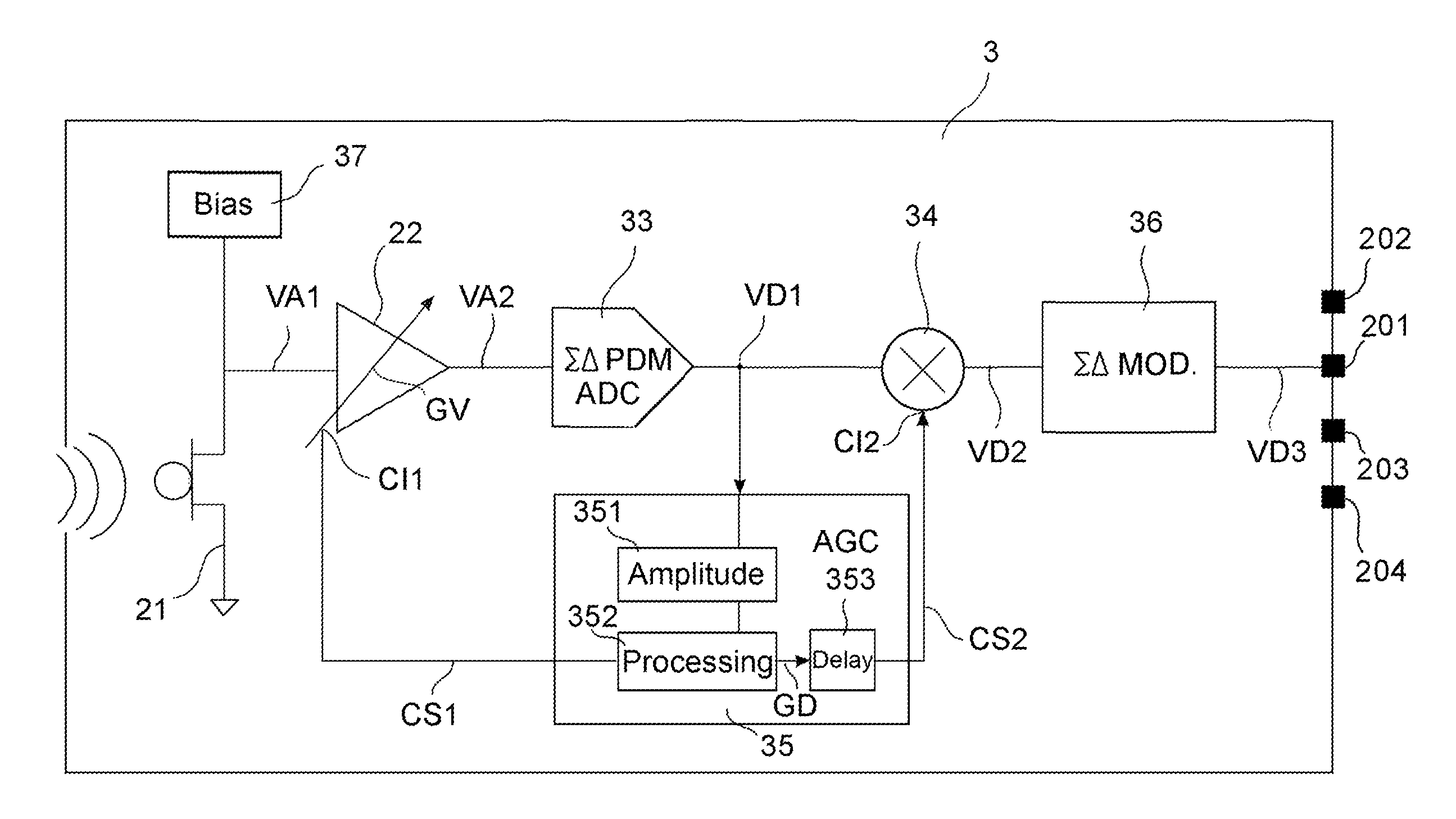
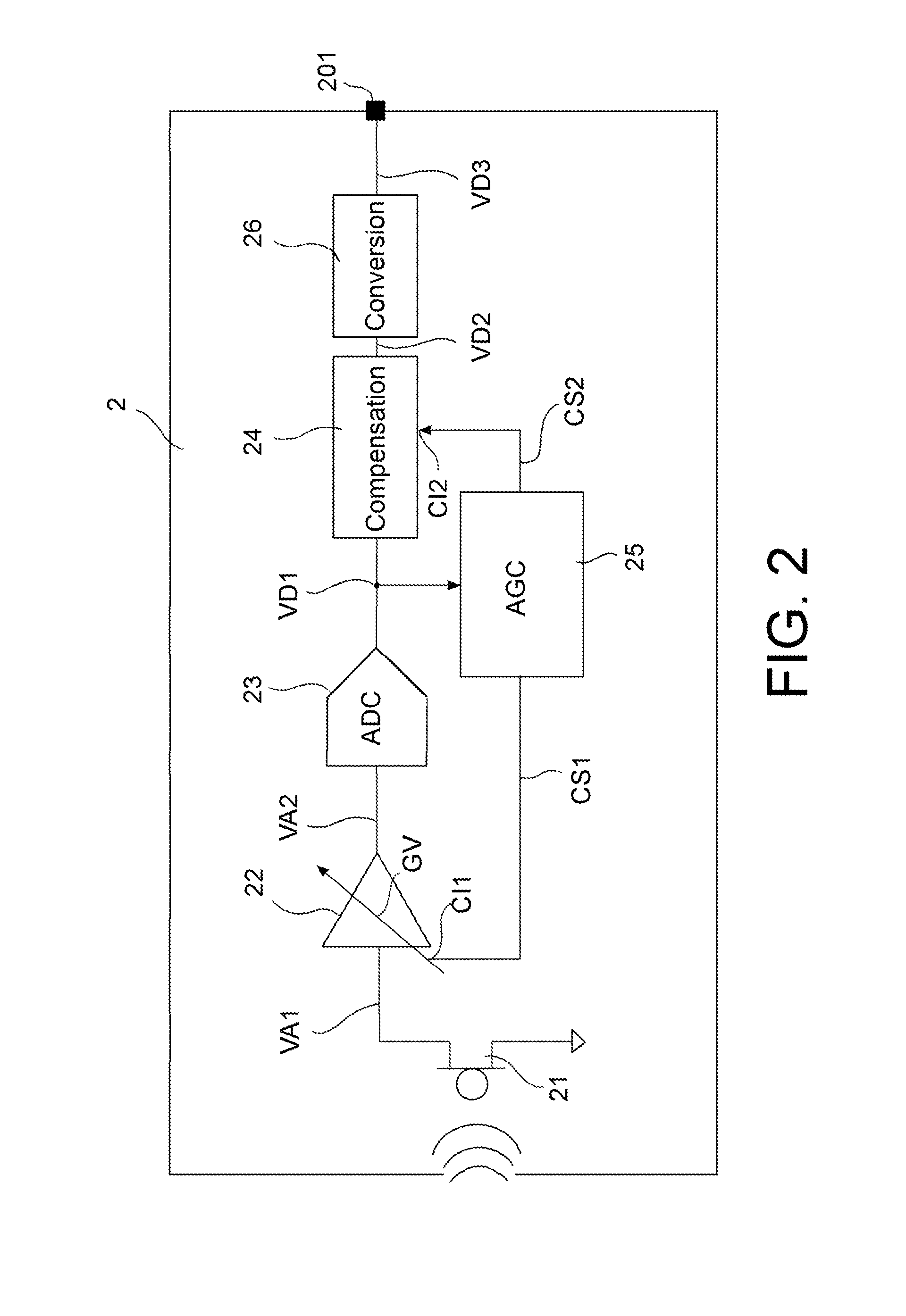
[0031]Diagrams of preferred embodiments of a digital microphone device according to the disclosure can be described with reference to FIGS. 2-4.

[0032]In particular, FIGS. 2-4 relate to a digital microphone device arranged to provide a single-bit Pulse Density Modulation (PDM) output signal, which is a typical feature for such a type of device.

[0033]With reference to FIG. 2, the digital microphone device 2 (or, simply, digital microphone 2) comprises a microphone 21, arranged to convert an acoustic input signal into an analog electrical signal VA1.

[0034]The digital microphone 2 further comprises a preamplifier 22, arranged to receive and amplify the analog electrical signal VA1, so as to obtain an amplified analog electrical signal VA2.

[0035]The preamplifier 22 is a variable-gain preamplifier, having a variable gain GV. The variations of the gain GV are controlled by, and depend on, a gain control signal CS1, which is available at a control input CI1 of the preamplifier 22.

[0036]More...


PUM


Abstract

The present disclosure refers to a digital microphone device providing a single-bit Pulse Density Modulation PDM output signal. The digital microphone comprises a microphone, arranged to convert an acoustic input signal into an analog electrical signal, and a preamplifier, having a variable gain, arranged to receive the analog electrical signal and to provide an amplified analog electrical signal, depending on the variable gain. The variable gain depends on a gain control signal. The digital microphone further comprises an Analog-to-Digital Converter block, arranged to receive the amplified analog electrical signal and to convert it into a respective digital signal; and a compensation block, arranged to receive the digital signal and to perform a digital operation on such digital signal, on the basis of a compensation signal, to generate a compensated signal. Furthermore, the digital microphone comprises an Automatic Gain Controller block 25, arranged to detect the digital signal and to generate said gain control signal, on the basis of the detected digital signal. The Automatic Gain Controller block is further arranged to generate the compensation signal, on the basis of the control signal, and to provide the compensation signal to the compensation block, to compensate a variation of the digital signal resulting from the variable gain of the preamplifier. Finally, the digital microphone device comprises a conversion block, arranged to receive the compensated signal and to convert it into the single-bit PDM output signal.

Description

BACKGROUND[0001]1. Technical Field[0002]The present disclosure relates to digital microphone devices and in particular to a digital microphone device with extended dynamic range. More specifically, the disclosure refers to an extended dynamic range digital microphone device providing a single-bit Pulse Density Modulation output signal.[0003]2. Description of the Related Art[0004]Digital microphone devices have recently emerged as an advantageous solution, especially for applications related to mobile phone devices.[0005]Traditionally, inside mobile phones or other electronic equipment, the microphones have been inserted as separate components and connected to the other printed circuit boards (PCBs) of the mobile phone device through mechanical systems (e.g., springs, mechanical pressure, etc.). Analog paths were provided on the printed circuit boards, in order to connect the microphones to the analog-to-digital conversion path.[0006]More recently a new approach is being used, with t...

Claims


Application Information

Patent Timeline
IPC IPC(8): H03G3/20
CPCH03G3/20H03G3/301H04R1/005H04R1/04H04R3/04H04R2499/11
Inventor PINNA, CARLOMECCHIA, ALESSANDROPESENTI, PAOLO
Owner STMICROELECTRONICS INT NV
Why Eureka
Try Eureka