Multiple Use Termination System

a termination system and multi-use technology, applied in the direction of coupling device connection, wellbore/well accessories, drilling pipes, etc., can solve the problems of short-circuit between different conductors within the junction and corresponding power failures, contaminating the oil in the motor, degrading the performance of the motor, etc., to increase the consistency and reliability of the connection, reduce the amount of training, and simple and extremely robust

Active Publication Date: 2014-11-13
BAKER HUGHES INC
View PDF11 Cites 20 Cited by
  • Summary
  • Abstract
  • Description
  • Claims
  • Application Information

AI Technical Summary

Benefits of technology

[0010]The present electrical connection system may be used, for example, to supply high-voltage electrical power to the motor of an ESP. This connection system is designed to provide a simple and extremely robust means to connect a power cable to the ESP. This technology can easily be adapted to provide the same type of functionality to low power applications such as tubing encapsulated conductor (TEC) wires used in downhole gauges or electrical control lines for other downhole tools. The use of a standardized connection configuration provides benefits such as allowing the use of standard components, reducing the amount of training required to work with the electrical connections, increasing consistency and reliability of the connections, and so on.
[0011]One embodiment comprises an electrical connector body which is adapted for use in a piece of downhole equipment, such as an ESP. The electrica

Problems solved by technology

As the motor is operated, small debris particles in the oil may accumulate at the pothead junction, eventually causing short-circuits between different conductors within the junction and corresponding power failures.
The same fluid paths that allow oil to flow out of the motor and into the pothead connection may also allow well fluids to leak into the motor, contaminating the oil in the motor and degrading its performance.
There are other types of problems with conventional electrical junctions as well.
The prob

Method used


Image

  • Multiple Use Termination System
  • Multiple Use Termination System
  • Multiple Use Termination System

Examples


Embodiment Construction

[0032]One or more embodiments of the invention are described below. It should be noted that these and any other embodiments described below are exemplary and are intended to be illustrative of the invention rather than limiting.

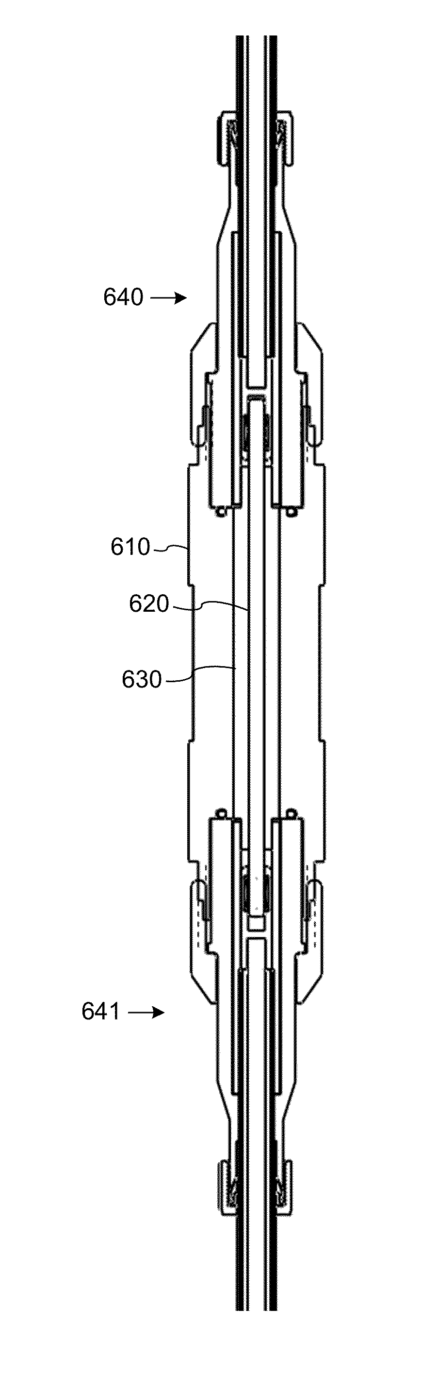
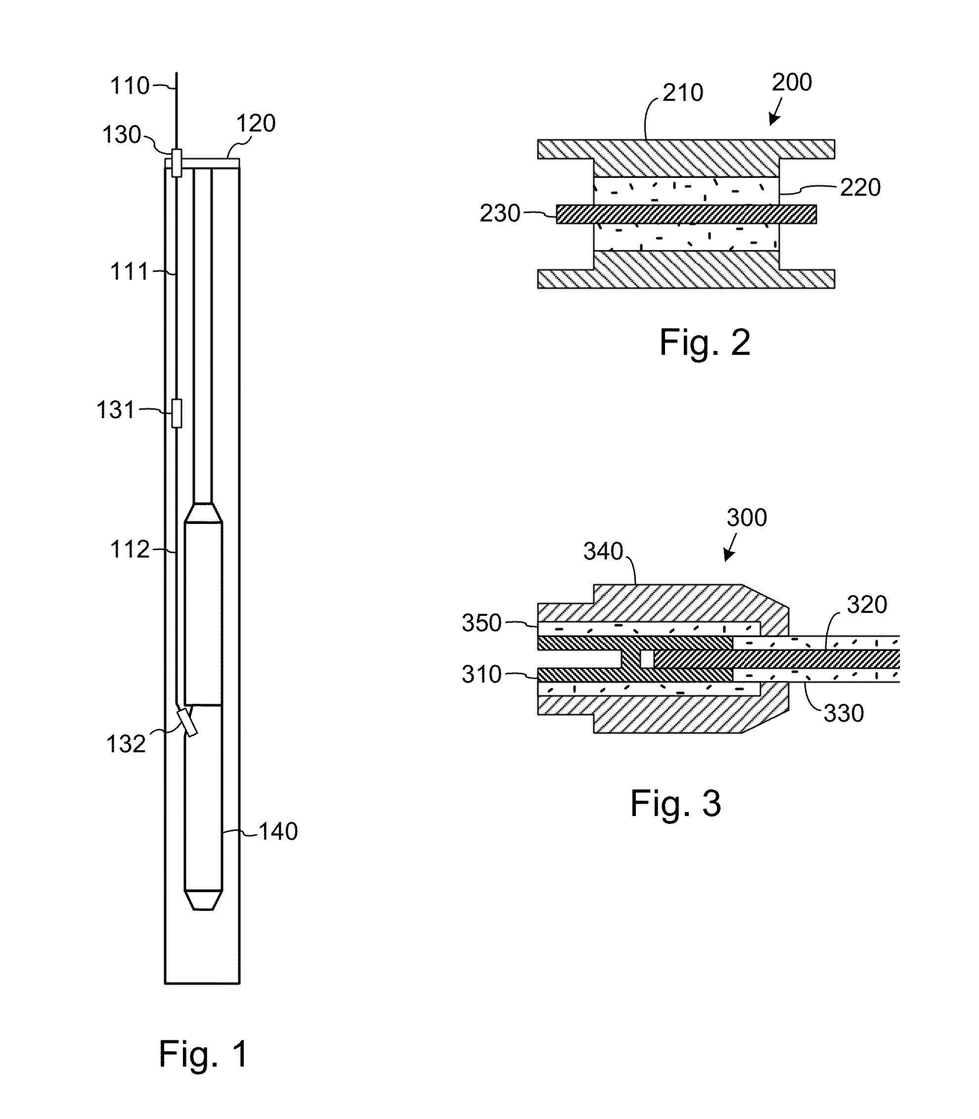
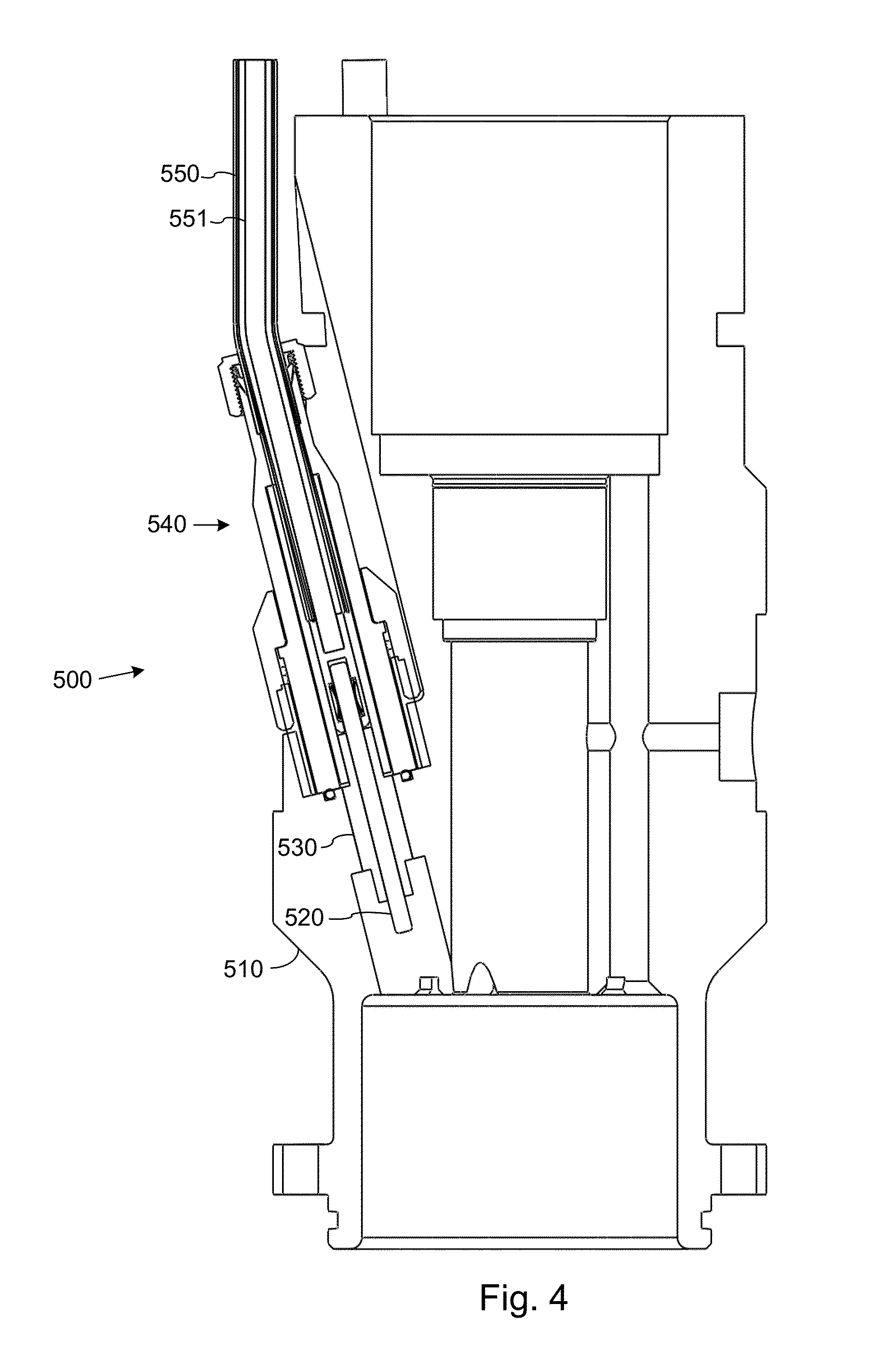
[0033]The present system provides a means to make electrical connections while at the same time forming robust pressure seals around the conductors and providing very high temperature resistance. One of the components is a connector body that has an insulator made of a ceramic, glass or other inert inorganic material. The insulator surrounds one or more conductors and insulates the conductors from a mechanical housing. The insulator forms a seal against both the conductors and the housing. The connector body may be configured to accommodate a second component—a standardized cable-end connector—at one or both ends of the connector body. The connection may be implemented in various different types of connections, such as motor connections (between a set of moto...


PUM

PropertyMeasurementUnit
aaaaaaaaaa

Abstract

Systems and methods for electrically connecting conductors of a downhole electric system using connector bodies that includes an outer housing, one or more inner conductors and an inorganic insulating material such as a glass-ceramic material which forms a fluid-tight seal between the outer housing and the inner conductor. The insulating material may be bonded to the outer housing and to the inner conductor. The insulating material may alternatively have an interference fit with the outer housing and the inner conductor. The connector bodies may have standardized connector interfaces to facilitate connection to complementary standardized connector interfaces on cable-end connectors, etc. Connector bodies may be formed as motor heads, mandrels for cable splices, penetrators, etc.

Description

CROSS-REFERENCE TO RELATED APPLICATIONS[0001]This application claims the benefit of co-owned U.S. Provisional Patent Application 61 / 822,169, filed May 10, 2013 by Semple, et al., which is incorporated by reference as if set forth herein in its entirety.BACKGROUND[0002]1. Field of the Invention[0003]The invention relates generally to power subsystems for downhole equipment such as electrical submersible pumps (ESP's), and more particularly to means for making robust connections between power system components the downhole equipment.[0004]2. Related Art[0005]Downhole equipment such as ESP systems are commonly installed in wells for purposes of producing fluids (e.g., oil) from the wells. Power suitable to drive the equipment is produced at the surface of the wells and is delivered to the equipment via power cables that extend into the wells. The power cables may have one or more electrical junctions, such as splices to motor leads and “pothead” connectors that couple the power cable t...

Claims


Application Information

Patent Timeline
IPC IPC(8): H01R43/20H01R13/52
CPCH01R43/20H01R13/5219H01R13/5205Y10T29/49117E21B43/128E21B17/00E21B17/028H01R13/523H01R13/533
Inventor SEMPLE, RYAN P.FREY, JEFFREY G.
Owner BAKER HUGHES INC
Why Eureka
Try Eureka