Fixation clamp

a clamping and fixing technology, applied in the field of fixing clamps, can solve problems such as bulky fixing systems, and achieve the effect of preventing erroneous jaw alignmen

Active Publication Date: 2014-11-13
STRYKER EURO OPERATIONS HLDG LLC
View PDF3 Cites 11 Cited by
  • Summary
  • Abstract
  • Description
  • Claims
  • Application Information

AI Technical Summary

Benefits of technology

The patent is for a device that prevents misalignment of jaws and improves their accuracy. This is achieved by using at least two orientation devices that help to position the jaws. The device also allows for a pivoting motion between the clamping assembly and the locking element, which can compensate for misalignments during the mounting process. The openings in the device have a channel or slot shape that can be adjusted in width for various purposes.

Problems solved by technology

This way of attaching pins or rods leads to bulky fixation systems.
However, past use has shown that in some applications the jaws of the clamping assembly have been orientated in an erroneous manner which led to unsatisfactory results.

Method used


Image

  • Fixation clamp
  • Fixation clamp
  • Fixation clamp

Examples


Embodiment Construction

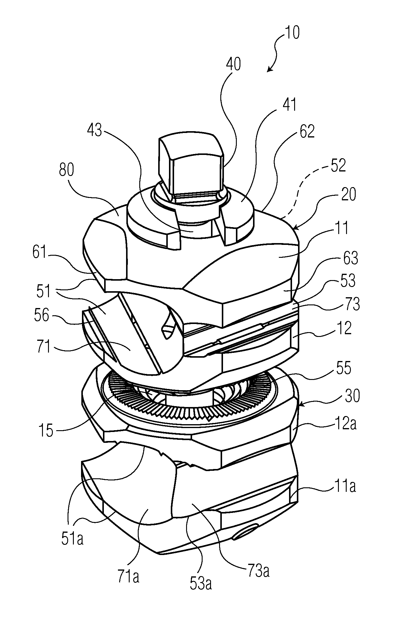
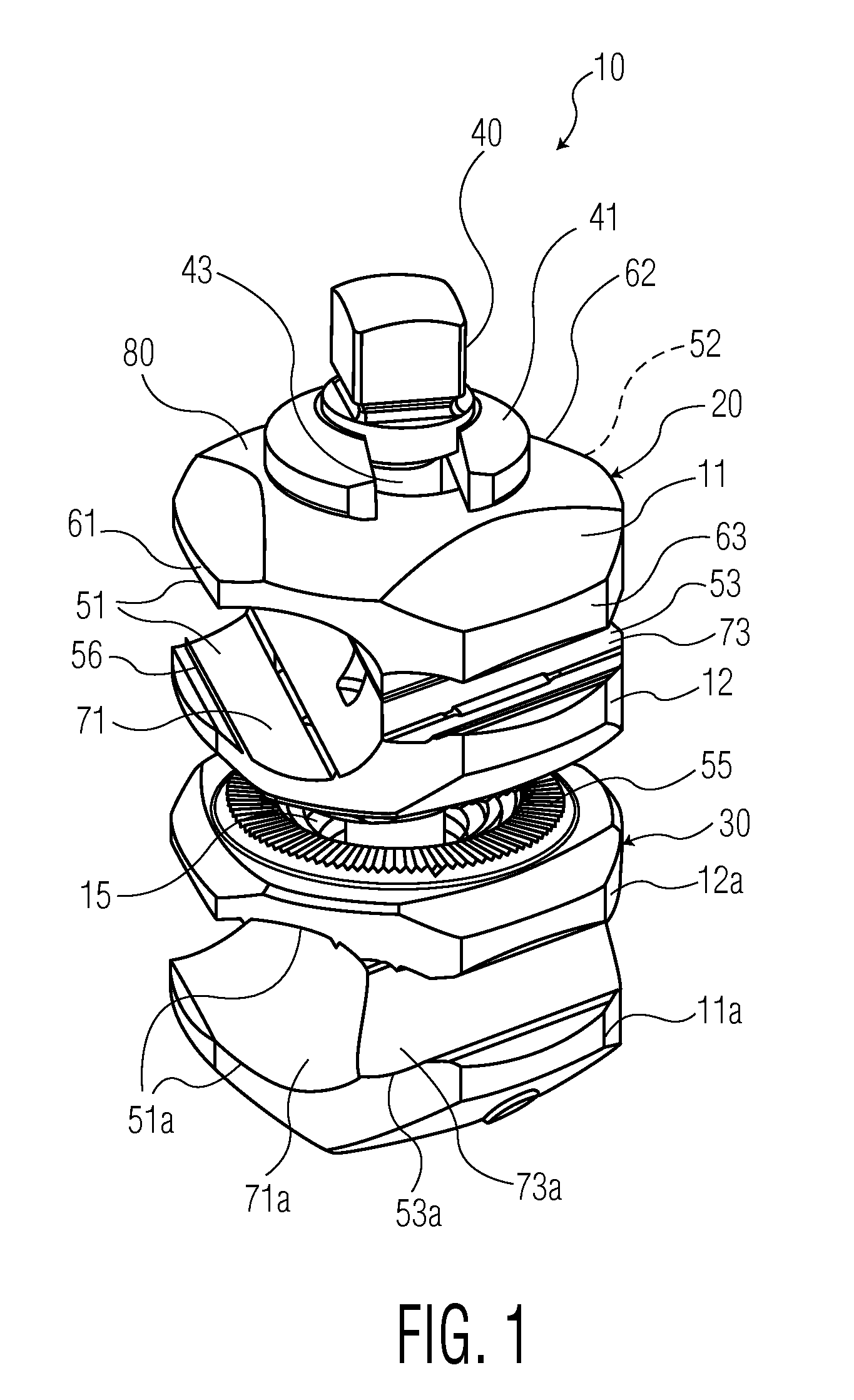
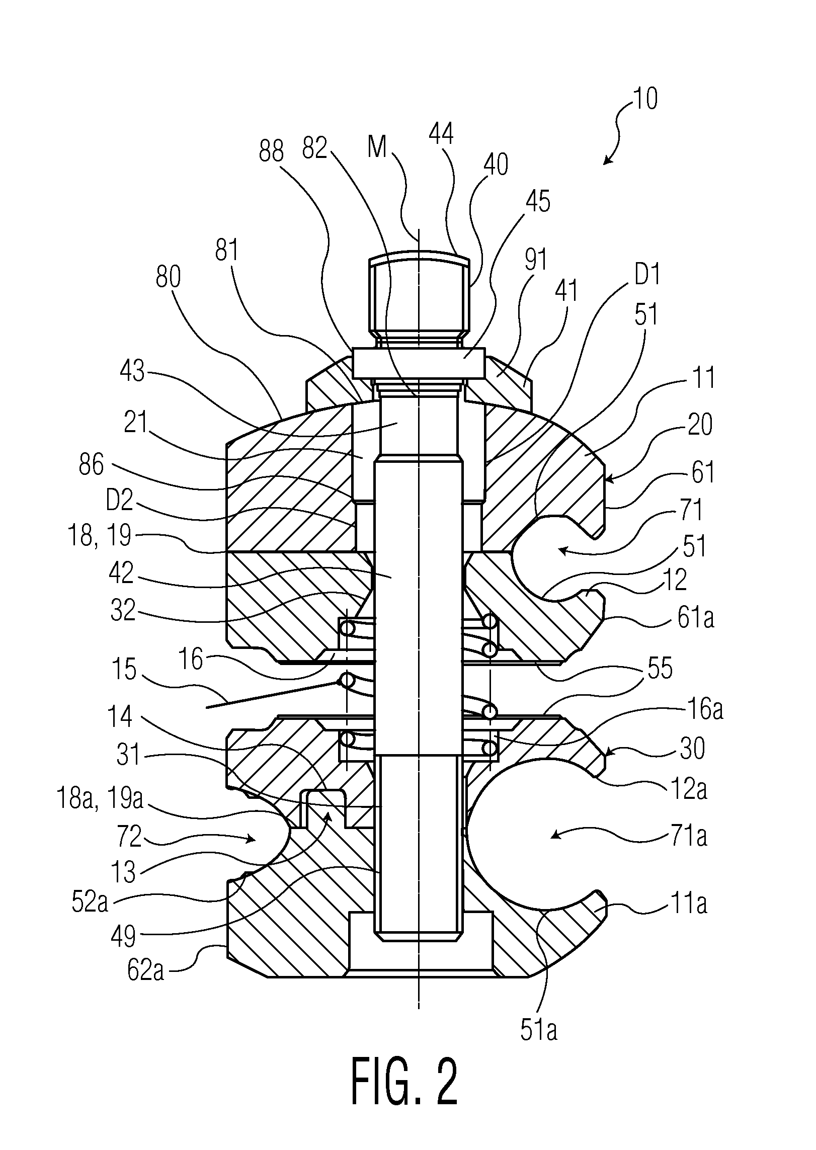
[0035]FIGS. 1 and 2 show a preferred first embodiment of a clamping element or fixation clamp 10 pursuant to the invention. The clamping element 10 consists of a first clamping assembly 20 and a second clamping assembly 30 and a locking element or shaft 40 which is positioned through bores 21, 31 within the two clamp assemblies 20, 30 along the longitudinal axis M of shaft 40. The shaft 40 is preferably a locking element adapted to allow closing the clamp assemblies 20 and 30. Shaft 40 enters a first jaw 11 through a washer 41.

[0036]The shaft 40 comprises a head portion 44, a reduced diameter portion 43 which is followed by a shaft portion 42 and a thread portion 49. The outer threaded portion 49 is adapted to be screwed into a complementary inner thread within the distal jaw 11a so that turning the head of the shaft 40 changes the longitudinal position of the shaft 40 against the lower jaw 11a, which allows opening or closing the entire clamp 10 against the force of a spring 15 pro...


PUM


Abstract

A fixation clamp for use in an external fixation system for holding bone fragments adjacent to each other with the help of fixation elements, has of at least one clamping assembly having at least one reception provided by means of grooves to accommodate a fixation element along the longitudinal axis of the reception. At least one locking element extends through the clamping assemblies for blocking the position of the clamping assemblies in a defined angular position. The clamping assembly comprises a first jaw and a second jaw which are in contact with each other via respective contact surfaces. The clamping assembly comprises at least two orientation devices that extend from and / or into said contact surfaces which at least two orientation devices serve to orient the first jaw with respect to the second jaw.

Description

CROSS-REFERENCE TO RELATED APPLICATION[0001]The present application is a continuation of U.S. patent application Ser. No. 13 / 302,559, filed Nov. 22, 2011, and claims priority from European Patent Application No. 10 194 945.1, filed Dec. 14, 2010, the disclosures of which are hereby incorporated herein by reference.BACKGROUND OF THE INVENTION[0002]The present invention relates to a fixation clamp and, more particularly, to a fixation clamp for use in an external fixation system for holding bone fragments adjacent each other. External fixation systems are widely used to connect two or more bone fragments to each other. Such systems comprise bone screws, pins, wires which are inserted directly into the bone material and these systems use external structural elements as fixation rods, bars and rings. In order to connect the rods and bars to form a rigid frame, fixation clamps are used. Furthermore, fixation clamps are used to connect the screws and pins to the rigid frame to specificall...

Claims


Application Information

Patent Timeline
Patent Type & Authority Applications(United States)
IPC IPC(8): A61B17/64
CPCA61B17/6466A61B17/6416A61B17/645A61B17/6458A61B2090/0811
Inventor DORAWA, KLAUSBUSCH, ADAMKUNG, CLAUDIO
Owner STRYKER EURO OPERATIONS HLDG LLC
Why Eureka
Try Eureka