Conditional monitoring of industrial systems

Inactive Publication Date: 2014-11-13
ABB (SCHWEIZ) AG
View PDF2 Cites 87 Cited by
  • Summary
  • Abstract
  • Description
  • Claims
  • Application Information

AI Technical Summary

Benefits of technology

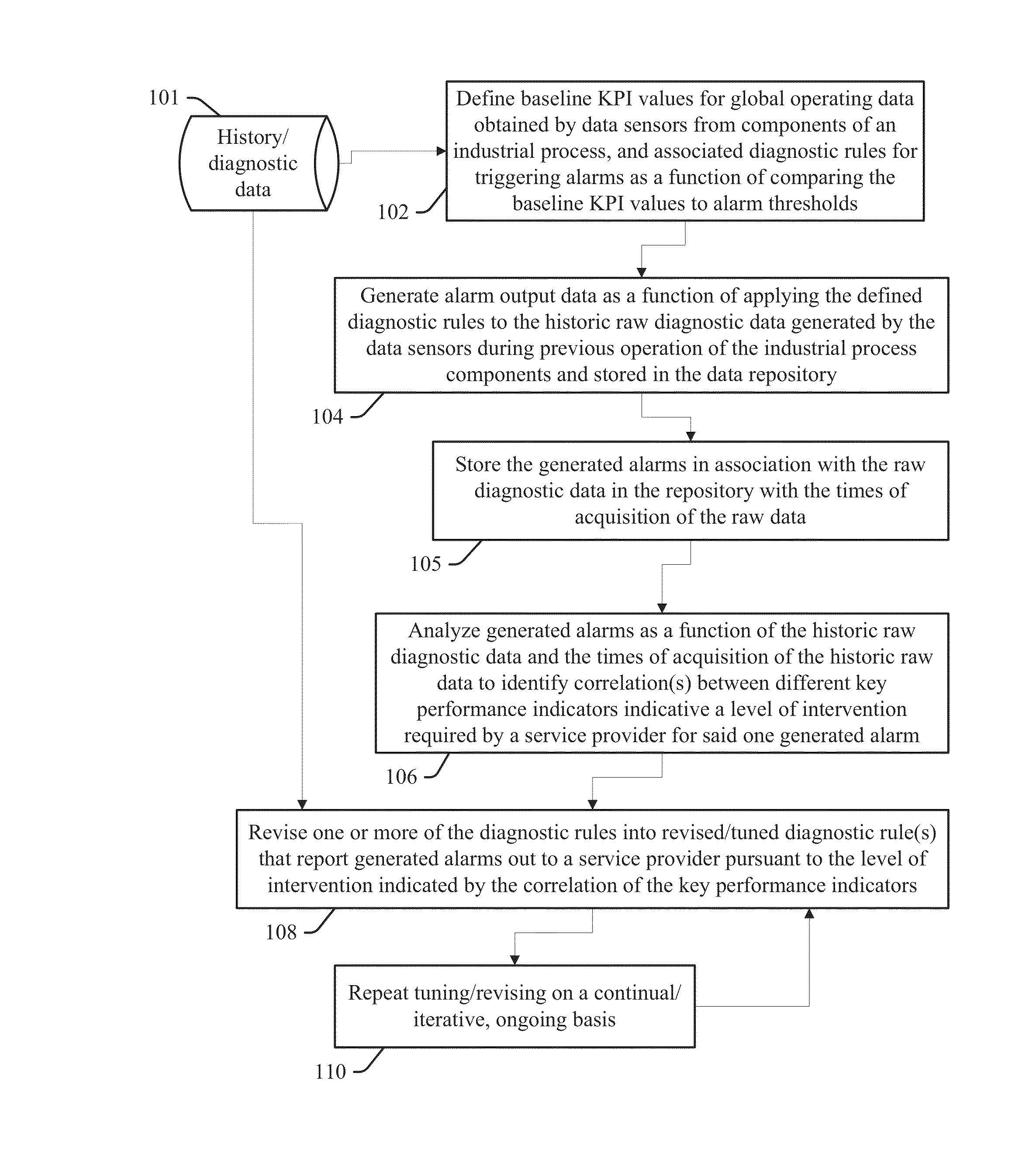
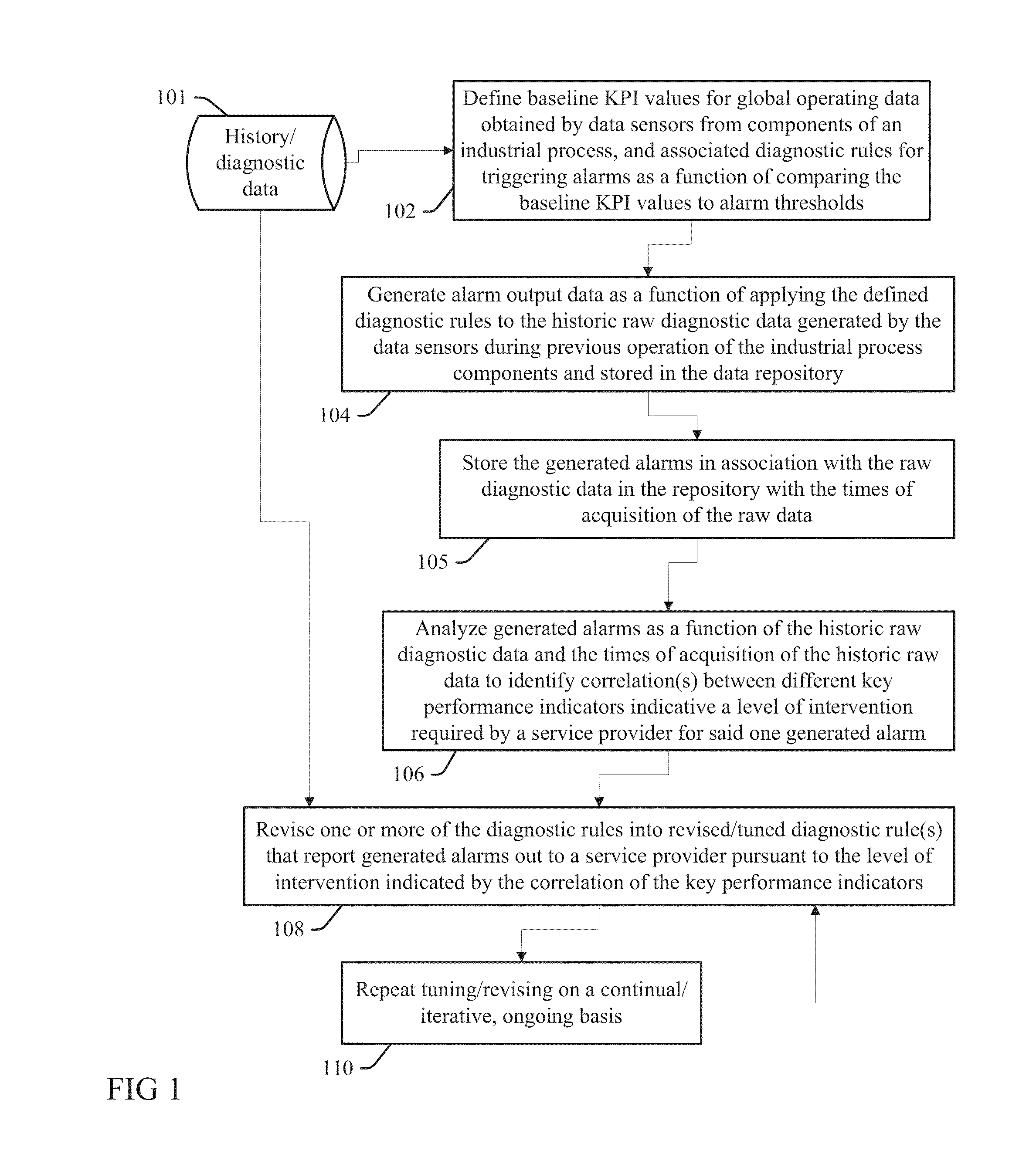
[0005]In one aspect of the present invention, a method for conditionally monitoring the performance of components of an industrial system as a function of key performance indicator data includes a processing unit defining baseline key performance indicator values for raw data obtained by data sensors from the operation of each of a plurality of components of an industrial process, and diagnostic rules for triggering alarms as a function of comparing the baseline key performance indicator values to alarm thresholds. The processing unit initiates generating of alarm output data as a function of applying the defined diagnostic rules to historic raw diagnostic data stored in a data repository that is generated by the data sensors during operation of the industrial process components. The processing unit initiates storing in the data repository of the generated alarms in association with the historic raw diagnostic data and with times of acquisition of the historic raw data and times of generation of the alarms. One or more of the generated alarms are analyzed as a function of the historic raw diagnostic data and the times of acquisition of the historic raw data to identify a correlation between different (first and second) ones of the key performance indicators that is indicative of a level of intervention required by a service provider for said one generated alarm. The processing unit thus revises one of the diagnostic rules into a revised diagnostic rule that initiates reporting of said one or more generated alarms out to a service provider pursuant to the level of intervention indicated by the correlation of the different, first and second key performance indicators.
[0006]In a

Problems solved by technology

However, large pluralities of different industrial processes implemented within a plant or other large enterprise present challenges to efficiently applying automated diagnostic tools and interpreting dat

Method used


Image

  • Conditional monitoring of industrial systems
  • Conditional monitoring of industrial systems
  • Conditional monitoring of industrial systems

Examples


Embodiment Construction

[0013]Any combination of one or more computer readable medium(s) may be utilized. The computer readable medium may be a computer readable signal medium or a computer readable storage medium. Examples of a computer readable storage medium exclude transitory, propagation or carrier wave signals or subject matter and include an electronic, magnetic, optical or semiconductor system, apparatus, or device, or any suitable combination of the foregoing. More specific examples (a non-exhaustive list) of the computer readable storage medium include the following: a portable computer diskette, a hard disk, a random access memory (RAM), a read-only memory (ROM), an erasable programmable read-only memory (EPROM or Flash memory), a portable compact disc read-only memory (CD-ROM), an optical storage device, a magnetic storage device, or any suitable combination of the foregoing. In the context of this document, a computer readable storage medium is not a transitory, propagation or carrier wave sig...


PUM


Abstract

Performances of components of an industrial system are conditionally monitored as a function of key performance indicator data by defining baseline key performance indicator values for raw data obtained by data sensors from the operation of the components, and diagnostic rules to triggering alarms by comparing baseline key performance indicator values to thresholds. Generated alarms are stored in association with the historic raw diagnostic data, times of acquisition of the historic raw data and times of generation of the alarms. Generated alarms are analyzed as a function of the said stored data and times to identify a correlation between different ones of the key performance indicators that are indicative of a required level of intervention, and the diagnostic rules are revised to initiate reporting of generated alarms pursuant to levels of intervention indicated by said correlations.

Description

CROSS-REFERENCE TO RELATED APPLICATION [0001]This application is a continuation, and claims priority, of a U.S. provisional patent application by Kevin Starr for CONDITIONAL MONITORING OF INDUSTRIAL SYSTEMS, filed in the U.S. Patent and Trademark Office on May 13, 2013 and assigned Ser. No. 61 / 822,561, confirmation number 4433.FIELD OF THE INVENTION [0002]Embodiments of the present invention relate to deploying on-site monitoring and diagnostic analysis that is responsive to conditional key performance indicators within an industrial system or process.BACKGROUND [0003]Service experts use various methods for collecting and analyzing customer diagnostic information for troubleshooting industrial process implementations. Specific implementations may occur only occasionally with regard to similar processes, data inputs and benchmarks, and therefore experts must often relearn an appropriate method and application for each new job.[0004]Automation services may provide software and hardwar...

Claims


Application Information

Patent Timeline
IPC IPC(8): G06F11/34
CPCG06F11/3409G05B23/0297G05B23/0235
Inventor STARR, KEVIN DALE
Owner ABB (SCHWEIZ) AG
Why Eureka
Try Eureka