Auto-calibration of blinds systems in buildings

a blinds and building technology, applied in the direction of door/window protective devices, wing accessories, sustainable buildings, etc., can solve the problems of system integration that is not sophisticated, mechanical parts that are subject to wear, and considerable energy reduction

Active Publication Date: 2014-11-20
SIGNIFY HLDG BV
View PDF7 Cites 15 Cited by
  • Summary
  • Abstract
  • Description
  • Claims
  • Application Information

AI Technical Summary

Benefits of technology

[0032]It should be noted that the inventive method may incorporate any of the features described above in association with the inventive system and has the same corresponding advantages.

Problems solved by technology

Each of these systems can be optimized within themselves, already leading to considerable energy reduction.
However due to business models and building construction processes, these systems have not been integrated in a sophisticated manner.
Blinds systems have many mechanical parts that are subject to wear.
Controlling blinds systems for commercial buildings automatically works quite well, but after a period of use the blinds cannot be properly controlled due to wear in the mechanical parts, e.g. due to stretching of the wires and increasing slag on rotating axes.
Such recalibration is time consuming and expensive and is therefore not done as often as would be desired for optimal performance.
The result is that blinds systems often are badly calibrated for relatively long periods of times.

Method used


Image

  • Auto-calibration of blinds systems in buildings
  • Auto-calibration of blinds systems in buildings
  • Auto-calibration of blinds systems in buildings

Examples


Embodiment Construction

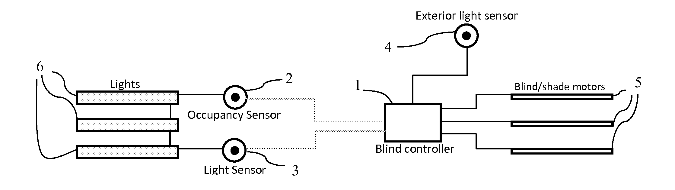
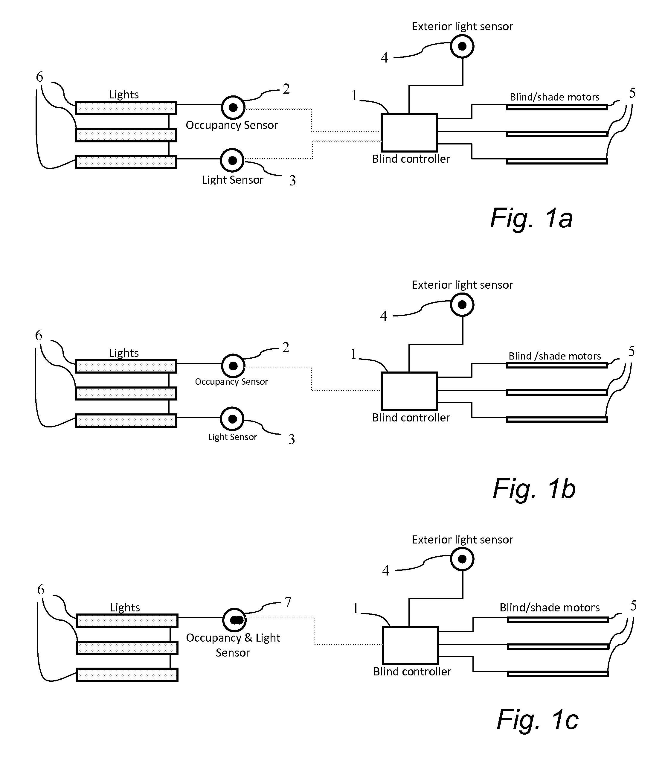
[0039]The occupancy sensor 2 and lighting sensor 3 information is integrated with the blinds control system. The occupancy and lighting sensors can have a direct link to the blinds system as shown in FIG. 1a. Alternatively, only the occupancy 2 or light sensor 3 can be connected to the blinds system, porting the communication between the other sensor and the blinds system controller 1 and managing communication between itself and the blinds system, as shown in FIG. 1b. A third, and most easy, option is to use an integrated occupancy and lighting sensor 7 and connect it directly to the blinds system, as shown in FIG. 1c. All these three solutions require a specific connector on the sensors 2, 3, 7 and the blinds control system and an agreed communication protocol.

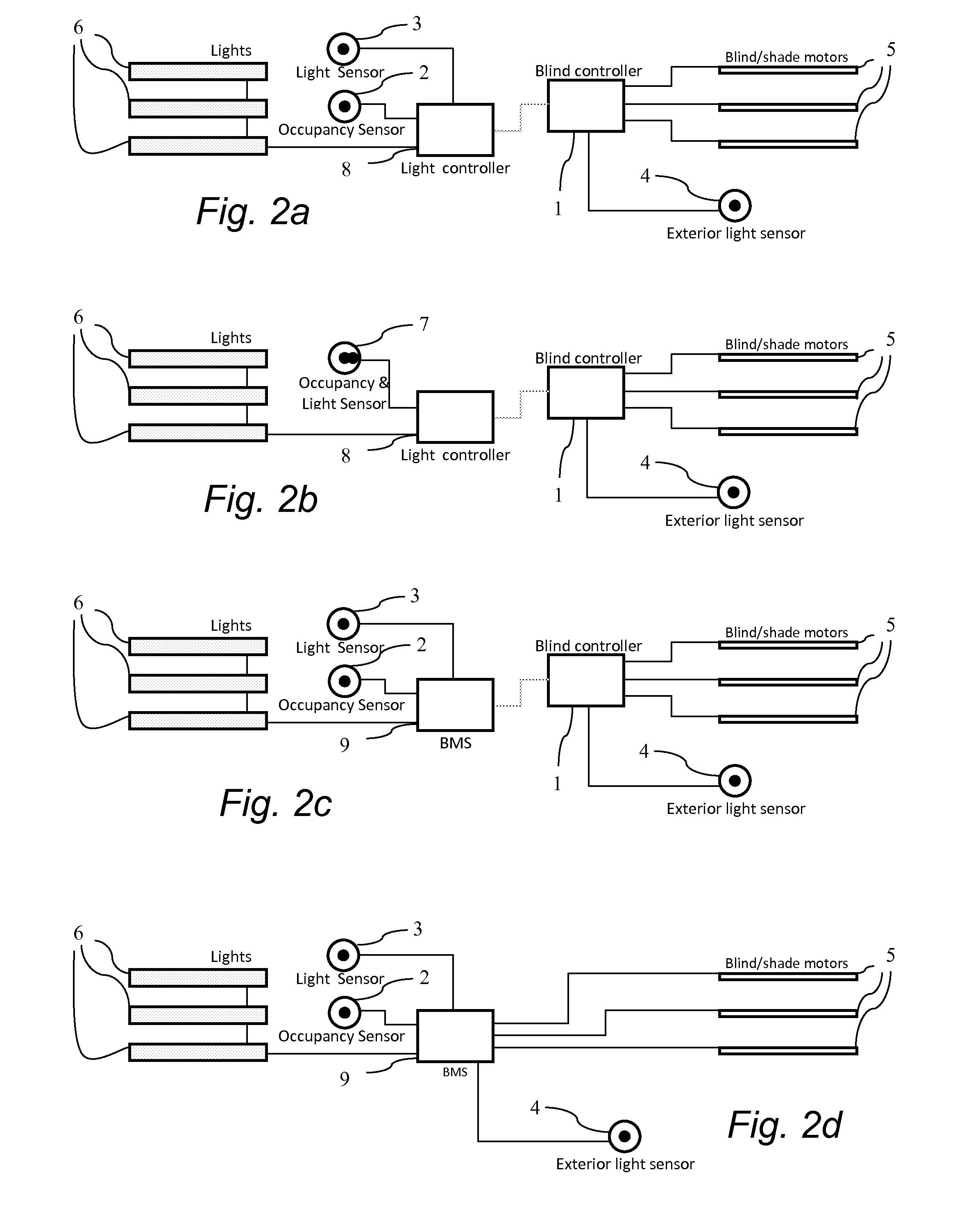
[0040]In case of a more advanced lighting system the occupancy information can be shared via a central lighting controller, or as part of a building management system (BMS) 9 as shown in FIG. 2a. In this case, existing netwo...


PUM


Abstract

The present invention relates to a control system for automatic calibration of a blinds system installed in a room, comprising: a controller (1, 8, 9) having a memory, a clock and a processor, an occupancy sensor (2, 7), an interior light sensor (3, 7), an exterior light sensor (4). The control system is characterised in that the control system is arranged to run an automated calibration of the blinds system when the exterior light sensor indicates an outside light level above a predetermined threshold, the occupancy sensor indicates that no person is present in the room, and a predetermined time has passed since the last calibration. The invention further relates to a method for automatic calibration of a blinds system installed in a room using a control system comprising a controller (1, 8, 9) having a memory, a clock and a processor, an occupancy sensor (2, 7), an interior light sensor (3, 7), an exterior light sensor (4), the method comprising the step of: running an automated calibration of the blinds system when the exterior light sensor (4) indicates an outside light level above a predetermined threshold, the occupancy sensor (2, 7) indicates that no person is present in the room, and a predetermined time has passed since the last calibration.

Description

FIELD OF THE INVENTION[0001]The present invention relates generally to auto-calibration of blinds systems in buildings. More particularly, the present invention relates to a control system for automatic calibration of a blinds system installed in a room as defined in the introductory parts of claim 1. The invention further also relates to a method for automatic calibration of a blinds system installed in a room.BACKGROUND OF THE INVENTION[0002]Commercial buildings account for about 30% to 40% of the world's energy consumption. It is therefore important to reduce the energy consumption of these buildings. On average, lighting accounts for 40% and heating, ventilation, and air conditioning (HVAC) accounts for 30% of the total building energy use. The remaining 30% is used for appliances, elevators etcetera. It is clear that lighting and HVAC are the main candidates for improvement and the easiest to address.[0003]The three main areas in managing lighting and HVAC are to manage interio...

Claims


Application Information

Patent Timeline
Patent Type & Authority Applications(United States)
IPC IPC(8): E06B9/68
CPCE06B9/68E06B9/32E06B2009/6809E06B2009/6827Y02A30/24Y02B80/00
Inventor DIEDERIKS, ELMO MARCUS ATTILA
Owner SIGNIFY HLDG BV
Why Eureka
Try Eureka