Systems and method for separating dimethyl ether from oil and water

a technology of dimethyl ether and oil, applied in the separation process, the nature of treatment water, borehole/well accessories, etc., can solve the problems of removing a maximum of 50% of dme, unable to produce dme uncontaminated oil, and difficult separation of dme from oil to achieve dme uncontaminated oil

Active Publication Date: 2014-11-20
SHELL USA INC
View PDF1 Cites 6 Cited by
  • Summary
  • Abstract
  • Description
  • Claims
  • Application Information

AI Technical Summary

Benefits of technology

[0007]In one aspect, the present invention is directed to a system comprising a gas-oil-water separation module, a dimethyl ether (DME) absorber, a water stripper, a liquid-liquid extractor, a water source, and an oil stripper. The gas-oil-water separation module is configured to receive a mixture comprised of DME, crude oil, water or brine, and a gas comprising alkane hydrocarbons, and is further configured to separate from the mixture: a gas comprising DME and alkane hydrocarbons, an oil phase comprising crude oil and DME, and an aqueous phase comprising water or brine and DME. The water stripper is operatively fluidly coupled to the gas-oil-water separation module configured to receive the separated aqueous phase therefrom. The water stripper is also operatively fluidly coupled to the DME absorber to receive a portion of a DME lean gas therefrom. The water stripper is configured to contact the separated aqueous phase received therein with the DME lean gas received therein to produce a DME lean water or brine containing less DME than the separated aqueous phase received therein and a first DME enriched gas containing more DME than the DME lean gas received therein, wherein the water stripper is operatively fluidly coupled to the DME absorber to provide the first DME enriched gas to the DME absorber. The oil stripper is operatively fluidly coupled to the gas-oil-water separation module and is configured to receive the separated oil phase comprising crude oil and DME therefrom. The oil stripper is also operatively fluidly coupled to the DME absorber to receive a portion of the DME lean gas therefrom. The oil stripper is configured to contact the separated oil phase received therein with the DME lean gas received therein to produce oil containing less DME that the separated oil phase received therein and to produce a second DME enriched gas containing more DME than the DME lean gas received therein, wherein the oil stripper is operatively fluidly coupled to the DME absorber to provide the second DME enriched gas to the DME absorber. The DME absorber is operatively fluidly coupled to the gas-oil-water separation module to receive at least a portion of the gas comprising DME and alkane hydrocarbons therefrom. The DME absorber is also operatively fluidly coupled to the water stripper to receive at least a portion of the first DME enriched gas therefrom, and is operatively fluidly coupled to the oil stripper to receive at least a portion of the second DME enriched gas therefrom. The DME absorber is also operatively fluidly coupled to the water source to receive water from the water source. The DME absorber is configured to contact the gas comprising DME and alkane hydrocarbons from the gas-oil-water separation module and the first and second DME enriched gases with water from the water source to produce: the DME lean gas, wherein the DME lean gas contains less DME than the gas from the gas-oil-water separation module; a DME absorber aqueous stream comprising water or brine and DME, wherein the DME absorber aqueous stream contains more DME than the water received by the DME absorber from the water source; and a DME absorber liquid hydrocarbon stream comprising DME and alkane hydrocarbons. The liquid-liquid extractor (LLE) is operatively fluidly coupled to the DME absorber to receive the DME absorber liquid hydrocarbon stream from the DME absorber and is operatively fluidly coupled to the water source to receive water or brine from the water source. The LLE is configured to contact the DME absorber liquid hydrocarbon stream and the water or brine received therein to produce a LLE liquid hydrocarbon stream and a LLE aqueous stream, wherein the LLE liquid hydrocarbon stream is comprised of alkane hydrocarbons and contains less DME than the DME absorber liquid hydrocarbon stream, and wherein the LLE aqueous stream is comprised of DME and water or brine.

Problems solved by technology

Separation of DME from oil to produce DME uncontaminated oil, however, has proven difficult.
However, this process only removes a maximum of 50% of the DME from the oil—which is insufficient to provide an oil uncontaminated with DME for refining.

Method used


Image

  • Systems and method for separating dimethyl ether from oil and water
  • Systems and method for separating dimethyl ether from oil and water
  • Systems and method for separating dimethyl ether from oil and water

Examples


Embodiment Construction

[0020]In the following detailed description, numerous specific details are set forth by way of examples in order to provide a thorough understanding of the relevant teachings. However, it should be apparent to those skilled in the art that the present teachings may be practiced without such details. In other instances, well known methods, procedures, and / or components, have been described at a relatively high-level, without detail, in order to avoid unnecessarily obscuring aspects of the present teachings.

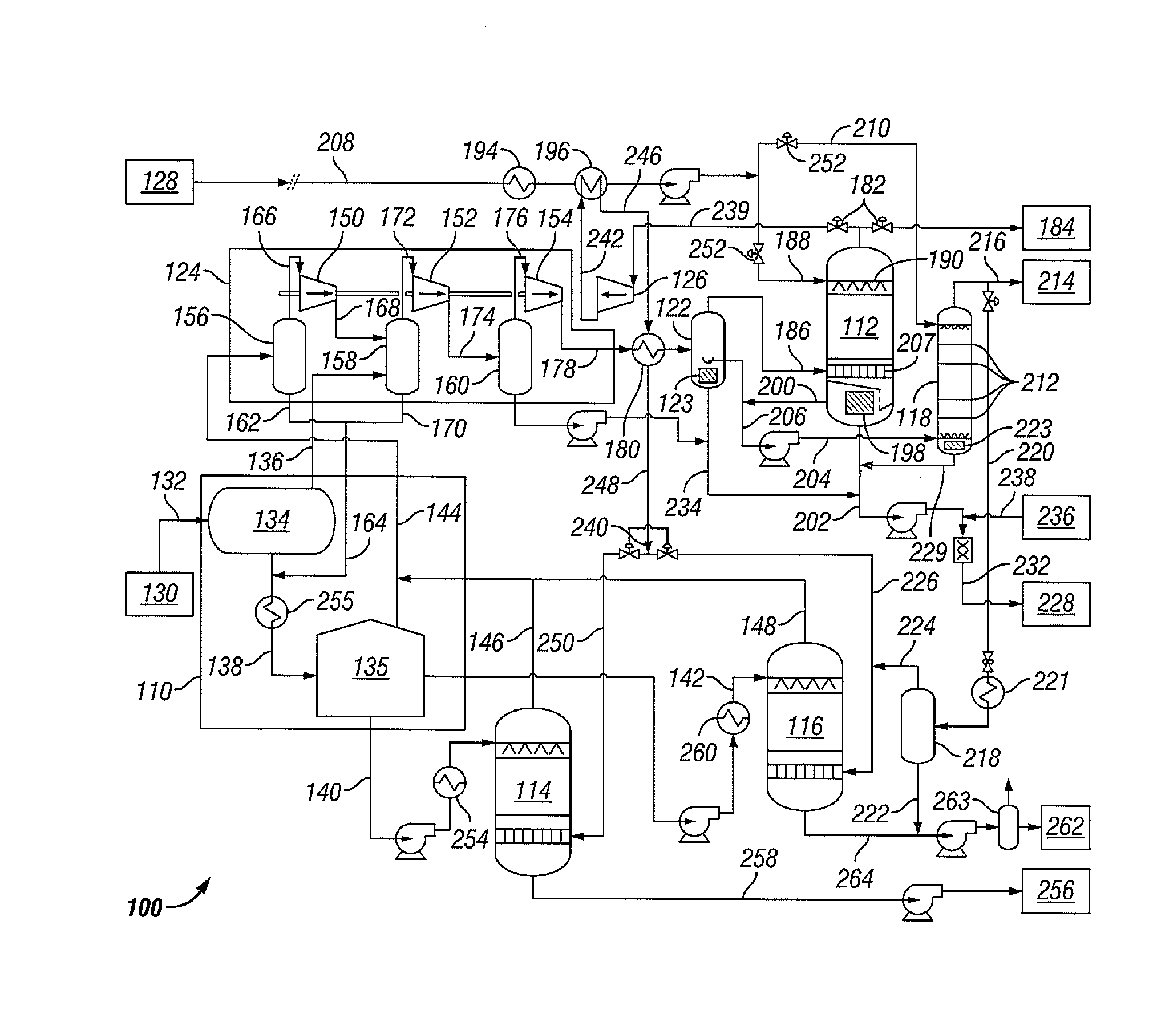
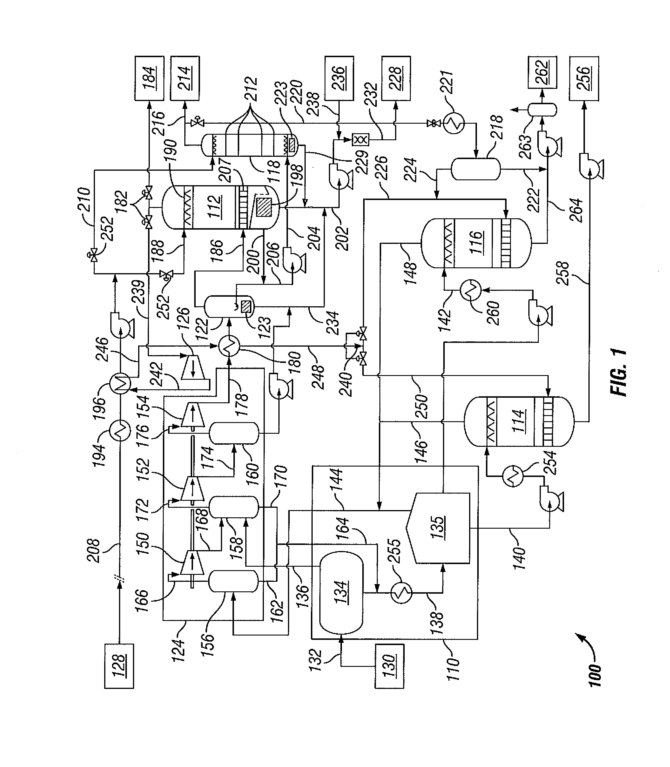
[0021]The present disclosure describes a system and method of separation of DME from a mixture of DME, crude oil, water or brine, and a gas comprised of alkane hydrocarbons. The system comprises a gas-oil-water separation module, a DME absorber, a water stripper, a liquid-liquid extractor, an oil stripper, and a water source. In a preferred embodiment, the system may include further components including a compressor, a high pressure separator, means for expanding a gas, and heating...


PUM

PropertyMeasurementUnit
pressureaaaaaaaaaa
pressureaaaaaaaaaa
pressureaaaaaaaaaa

Abstract

A system is provided for removing dimethyl ether (DME) from oil, water or brine and gas that includes a gas-oil-water separation module, a DME absorber, a water stripper, a liquid-liquid extractor, a water source, and an oil stripper, and a process is provided for separating DME from a mixture of DME, crude oil, water or brine, and a gas containing alkane hydrocarbons. A DME lean oil containing at most 1 ppmwt may be produced by the process.

Description

PRIORITY[0001]This application claims priority from U.S. Provisional Application Ser. No. 61 / 824,636 filed May 17, 2013, which is hereby incorporated by references in its entirety.FIELD OF THE INVENTION[0002]The present invention is directed to a system and a method for separating dimethyl ether from a mixture of dimethyl ether, oil, and water or brine, and a gas comprising alkane hydrocarbons, and particularly for separating dimethyl ether from mixtures of dimethyl ether, oil, and water or brine, and gas produced from an oil-bearing formation.BACKGROUND OF THE INVENTION[0003]Enhanced Oil Recovery (EOR) may be used to increase oil recovery in oil fields worldwide. One type of EOR process utilizes one or more chemical solvents to enhance oil recovery from an oil-bearing formation. The chemical solvent is selected to be soluble or miscible with oil in the formation and to have a lower viscosity than the oil in the formation so that the viscosity of the oil in the formation is reduced ...

Claims


Application Information

Patent Timeline
Patent Type & Authority Applications(United States)
IPC IPC(8): B01D53/14B01D19/00E21B43/40B01D53/18
CPCB01D53/1406B01D53/18B01D2011/005B01D53/1487E21B43/40B01D19/0073B01D11/04B01D19/0005B01D19/0036C02F1/20C02F1/26C02F2103/365C10G7/04B01D2252/103B01D2256/24
Inventor KOOIJMAN, HENDRIK ADRIAANBURGGRAAF, GOSINA GEERTRUIDA
Owner SHELL USA INC
Why Eureka
Try Eureka