Condensing mode operation of gas-phase polymerization reactor

a gas-phase polymerization and condensing mode technology, which is applied in the field of gas-phase polymerization reactor condensing mode operation, can solve the problems of complete reactor shut-down, limited fluid velocity in the reactor, and increasing the reaction rate in the fluidized bed reactor

Inactive Publication Date: 2005-06-23
UNIVATION TECH LLC
View PDF12 Cites 109 Cited by
  • Summary
  • Abstract
  • Description
  • Claims
  • Application Information

AI Technical Summary

Benefits of technology

[0008] There is disclosed a continuous gas fluidized bed polymerization process for the production of a polymer from a monomer including continuously passing a gaseous stream comprising the monomer through a fluidized bed reactor in the presence of a catalyst under reactive conditions; withdrawing a polymeric product and a stream comprising unreacted monomer gases; cooling said stream comprising unreacted monomer gases to form a mixture compr

Problems solved by technology

The primary limitation on increasing the reaction rate in a fluidized bed reactor is the rate at which heat can be removed from the polymerization zone.
The fluid velocity in the reactor is limited to prevent excessive entrainment and carry-over of solids.
This assumption was predicated on the belief that the introduction of liquid into a gas phase fluidized bed reactor would inevitably result in plugging of the distribution plate, if one is employed, less-than-adequate fluidization inside the reactor and accumulation of liquid at the bottom of the reactor which would

Method used


Image

  • Condensing mode operation of gas-phase polymerization reactor
  • Condensing mode operation of gas-phase polymerization reactor

Examples


examples

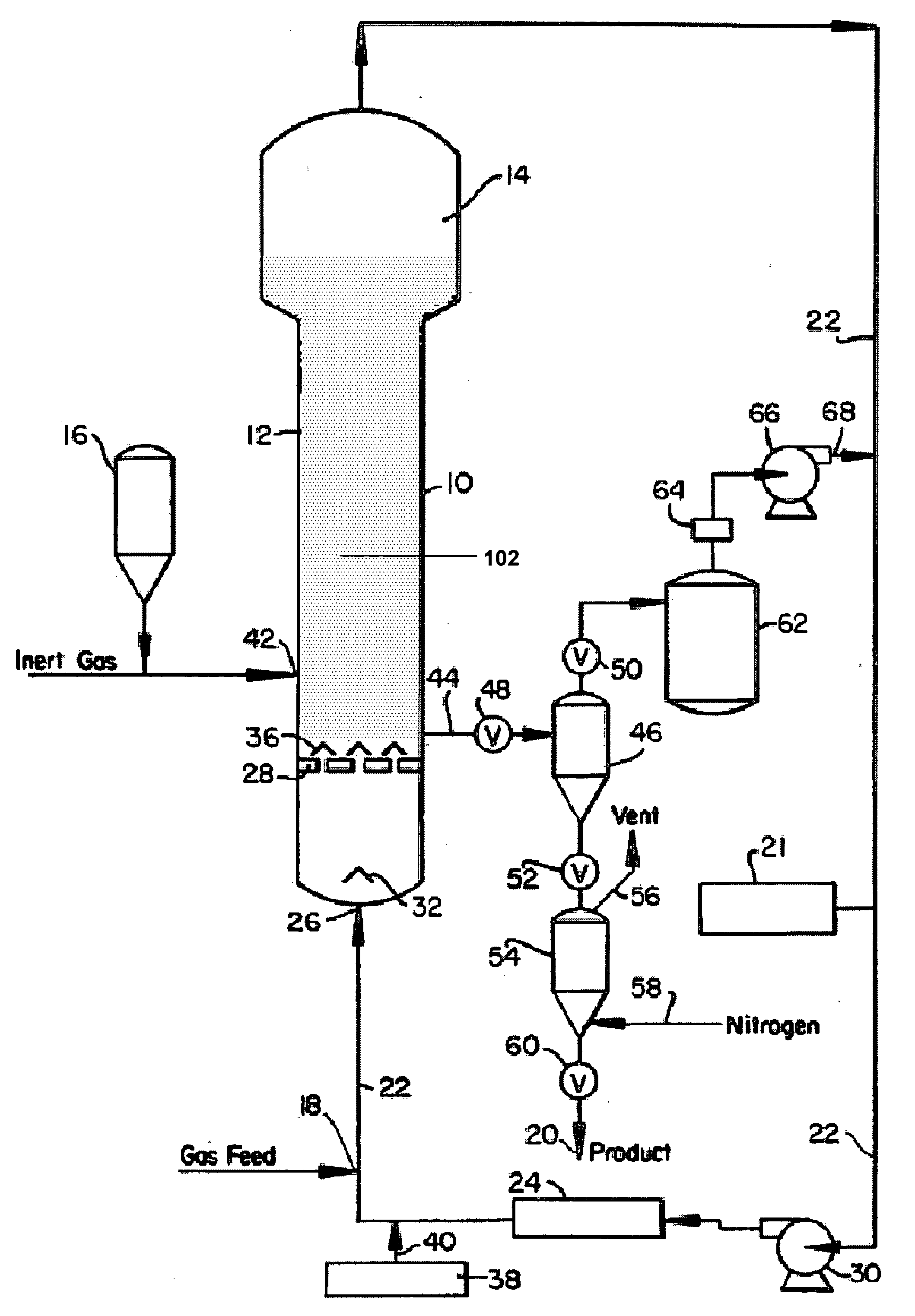
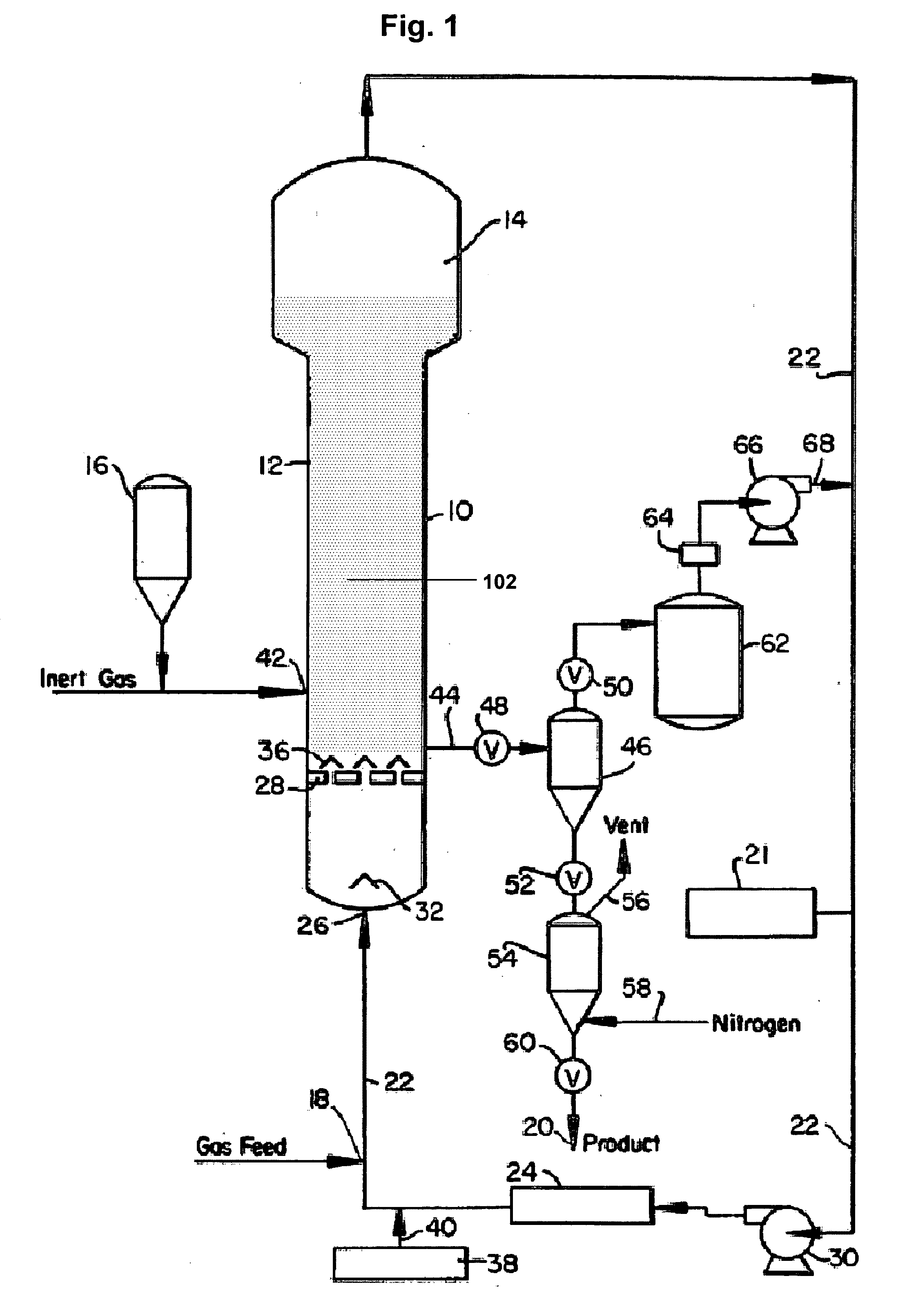
[0077] All the following examples are related to commercial scale operations conducted in a gas phase fluidized bed polymerization reactor similar to the one as shown and described above in FIG. 1. The reactor used for these examples have a diameter of 14.5 feet (4.42 m). Detailed operating conditions and operation results of these examples are listed in Table 2.

[0078] Examples 1, 4 and 6 are comparative examples using iso-pentane as ICA, running at conditions very close to their stickiness limits. Therefore, the production rates are the maximum ones can be achieved under those conditions.

[0079] Examples 2, 3, 5 and 7 employ low-solubility ICAs. It can be seen from Table 2 that significant increase of production rate is achieved, although they are not necessarily operated near the stickiness limits.

TABLE 2Example1234567ProductLLDPELLDPELLDPELLDPELLDPEHDPEHDPEComonomer1-butene1-butene1-butene1-hexexe1-hexexe1-hexexe1-hexexeCatalystZiegler-Ziegler-Ziegler-MetalloceneMetalloceneZie...

example # 1

*relative to Example #1

**relative to Example #4

***relative to Example #6

****determined using ASTM D1238

[0080] In one preferred embodiment, n-butane is used as an ICA to produce metallocene catalyzed linear low density polyethylene in a reactor at 350 psig and 85° C., as more fully set forth in Example 5 above. In another preferred embodiment, iso-butane is used as an ICA to produce Ziegler-Natta catalyzed linear low density polyethylene in a reactor at 350 psig and 91° C., as more fully set forth in Example 3 above.

[0081] Although illustrative embodiments have been shown and described, a wide range of modification, changes and substitution is contemplated in the foregoing disclosure. In some instances, some aspects of the illustrative embodiments may be employed without a corresponding use of the other aspects. Accordingly, it is appropriate that the appended claims be construed broadly and in a manner consistent with the scope of the invention.

[0082] Unless otherwise indicated...


PUM

PropertyMeasurementUnit
Temperatureaaaaaaaaaa
Weightaaaaaaaaaa

Abstract

A continuous gas fluidized bed polymerization process for the production of a polymer from a monomer including continuously passing a gaseous stream comprising the monomer through a fluidized bed reactor in the presence of a catalyst under reactive conditions; withdrawing a polymeric product and a stream comprising unreacted monomer gases; cooling said stream comprising unreacted monomer gases to form a mixture comprising a gas phase and a liquid phase and reintroducing said mixture into said reactor with sufficient additional monomer to replace that monomer polymerized and withdrawn as the product, wherein said liquid phase is vaporized, and wherein the stream comprises an induced condensing agent selected from the group consisting of alkanes, cycloalkanes, and mixtures thereof, the induced condensing agent having a normal boiling point less than 25° C.

Description

FIELD OF THE INVENTION [0001] The present embodiments relate to processes for condensing mode operation of a gas-phase polymerization reactor. More specifically, the present embodiments are directed to the use of low boiling point induced condensing agents or induced condensing agents having low solubilities in a polymer, which allow the introduction of more induced condensing agent into the reactor to promote more heat removal than conventional induced condensing agents. BACKGROUND OF THE INVENTION [0002] The condensing mode of operation in gas-phase polymerization reactors significantly increases the production rate or space time yield by providing extra heat-removal capacity through the evaporation of condensates in the cycle gas. Additional condensation is often promoted to extend the utility of condensed mode operation by adding an induced condensing agent (“ICA”) into the reactor. The amount of ICA that can be introduced into the reactor, however, must be kept below the “stick...

Claims


Application Information

Patent Timeline
IPC IPC(8): C08F210/16
CPCC08F210/16C08F2/34C08F210/14C08F2500/12C08F2500/07C08F210/08
Inventor CAI, PING P.OLSON, ROBERT DARRELLEISINGER, RONALD STEVENHUSSEIN, FATHI DAVIDHAGERTY, ROBERT OLDSBLOOD, MARK WILLIAMS
Owner UNIVATION TECH LLC
Why Eureka
Try Eureka