LED Switch Circuitry for Varying Input Voltage Source

a technology of switching circuits and input voltage sources, applied in the direction of lighting apparatus, electrical equipment, light sources, etc., can solve the problem of significant power loss in current source g

Active Publication Date: 2014-11-20
HUIZHOU LIGHT ENGINE LTD
View PDF3 Cites 7 Cited by
  • Summary
  • Abstract
  • Description
  • Claims
  • Application Information

AI Technical Summary

Benefits of technology

[0005]In accordance with a first aspect of the present invention, an LED array switching apparatus, comprises: a plurality of LED segments D1 to Dn connected in series, each LED segment having a forward voltage; a voltage supply coupled to the plurality of LED segments; and a plurality of constant current sources G1 to Gn, coupled to outputs of LED segments D1 to Dn, respectively, each of the constant current sources being switchable between a current regulating state and an open state such that as the voltage of the voltage supply increases, LED segments are switched on and lit to form a higher forward voltage LED string, and as the voltage of the voltage supply decreases, segments are switched off and removed from the LED string starting with the most recently lit segment.

Problems solved by technology

However, if voltage of input voltage source V is much higher than the forward voltage of D, a large voltage drop is present in current source G. Such an occurrence may cause a significant power loss in current source G, particularly if current source G is a linear current source.

Method used


Image

  • LED Switch Circuitry for Varying Input Voltage Source
  • LED Switch Circuitry for Varying Input Voltage Source
  • LED Switch Circuitry for Varying Input Voltage Source

Examples


Embodiment Construction

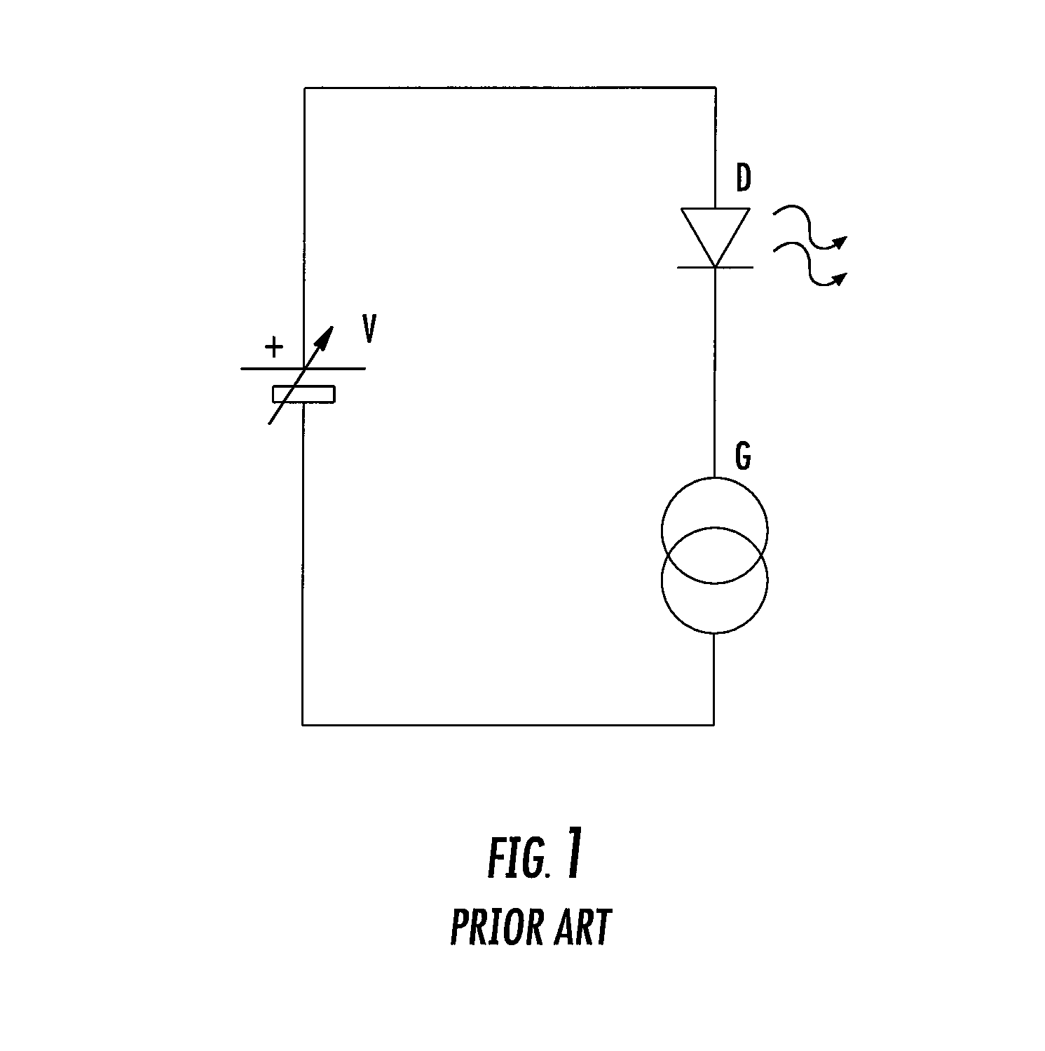
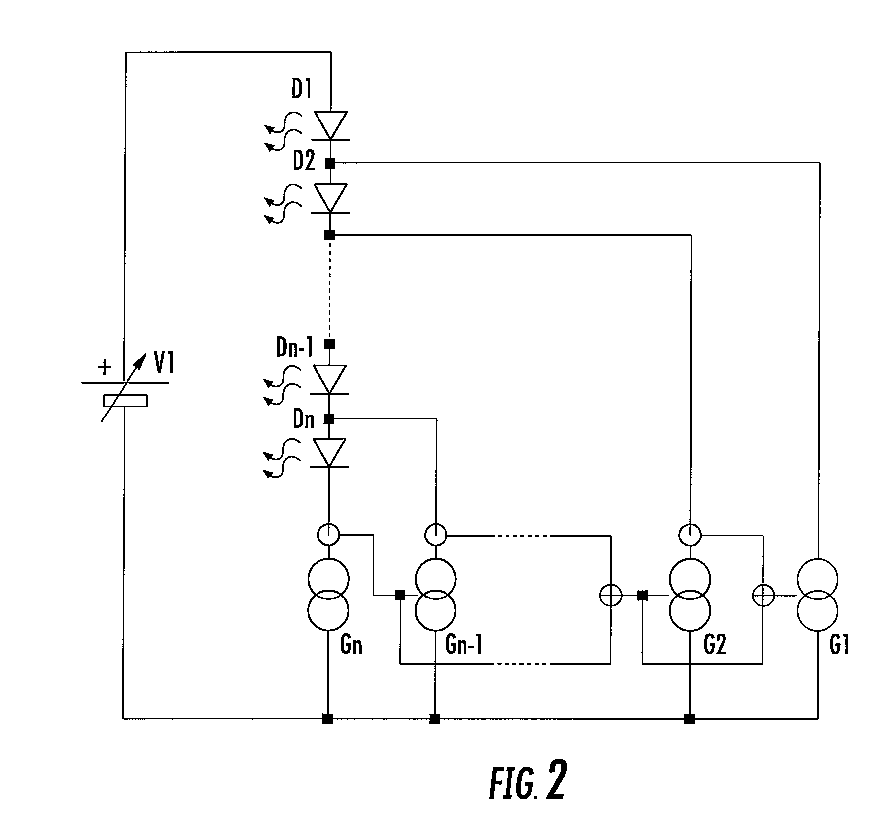
[0032]FIGS. 2-14 illustrate aspects of preferred embodiments of LED array switching apparatus. For an LED lighting device to work using a varying input voltage source, such as a rectified AC source, the switching apparatus in accordance with the present invention divides the LED string into a series of multiple segments. When the input voltage is low, only the first LED segment is lit up. As the input voltage increases, subsequent LED segments are switched in series to form a higher forward voltage string. Contrarily, if the input voltage decreases, the sequence is reversed and segments are removed from the string starting with the last light-up segment.

[0033]FIG. 2 shows the functional blocks of the proposed circuitry. It is assumed that the LED string is divided into n LED segments D1 to Dn, where n>1. Each LED segment may consist of one or more LEDs. G1 to Gn are constant current sources which can be disabled, that is, changed to an open circuit condition, by current sense signal...


PUM


Abstract

An LED array switching apparatus, comprises: a plurality of LED segments D1 to Dn connected in series, each LED segment having a forward voltage; a voltage supply coupled to the plurality of LED segments; and a plurality of constant current sources G1 to Gn, coupled to outputs of LED segments D1 to Dn, respectively. Each of the constant current sources is switchable between a current regulating state and an open state such that as the voltage of the voltage supply increases, LED segments are switched on and lit to form a higher forward voltage LED string, and as the voltage of the voltage supply decreases, segments are switched off and removed from the LED string starting with the most recently lit segment.

Description

CROSS-REFERENCE TO RELATED APPLICATIONS[0001]This utility application is a continuation of U.S. Ser. No. 12 / 955,030, filed Nov. 29, 2010, which claims priority to and benefit of U.S. Provisional Patent Application No. 61 / 373,058, filed Aug. 12, 2010, the entirety of which is incorporated by reference herein.BACKGROUND OF THE INVENTION[0002]The present invention relates to switching circuitry used in driving LED light sources. In particular, circuitry in which LEDs are driven by a regulated current source.[0003]Conventionally, LEDs may be driven by a current source that regulates the current flowing through the LEDs and hence maintains the light output of the LEDs. FIG. 1 shows a typical circuit for driving an LED circuit in which V is an input voltage source, D is representative of a string of LEDs and G is a current source. In such a circuit, in order for current to flow through D, the source input voltage of V must be higher than the forward voltage of the LEDs D.[0004]However, if...

Claims


Application Information

Patent Timeline
Patent Type & Authority Applications(United States)
IPC IPC(8): H05B33/08H05B44/00
CPCH05B33/083H05B45/48
Inventor LEUNG, WA HINGSIU, JOHNNY
Owner HUIZHOU LIGHT ENGINE LTD
Why Eureka
Try Eureka