
Semiconductor device and manufacturing method thereof

A semiconductor and device technology, applied in the field of semiconductor devices and their manufacturing, can solve the problems of increased chip cost, inability to obtain sufficient di/dt capability, difficulties, etc., and achieve the effect of low forward voltage

Active Publication Date: 2005-11-30
FUJI ELECTRIC CO LTD
View PDF5 Cites 4 Cited by
  • Summary
  • Abstract
  • Description
  • Claims
  • Application Information

AI Technical Summary

Problems solved by technology

This complicates the production process and leads to an increase in chip cost
[0018] Furthermore, although a region with short-lived carriers is formed locally in the depth direction of the chip surface or near the surface by using helium ions or protons, sufficient di / dt capability cannot be obtained
Further, in the case of heavy metals being diffused as lifetime inhibitors, it is difficult to control the depth of diffusion of the heavy metals

Method used


Image

  • Semiconductor device and manufacturing method thereof
  • Semiconductor device and manufacturing method thereof
  • Semiconductor device and manufacturing method thereof

Examples


Embodiment Construction

[0039] Hereinafter, preferred embodiments of a semiconductor device and a method of manufacturing the same according to the present invention will be explained in detail with reference to the accompanying drawings.

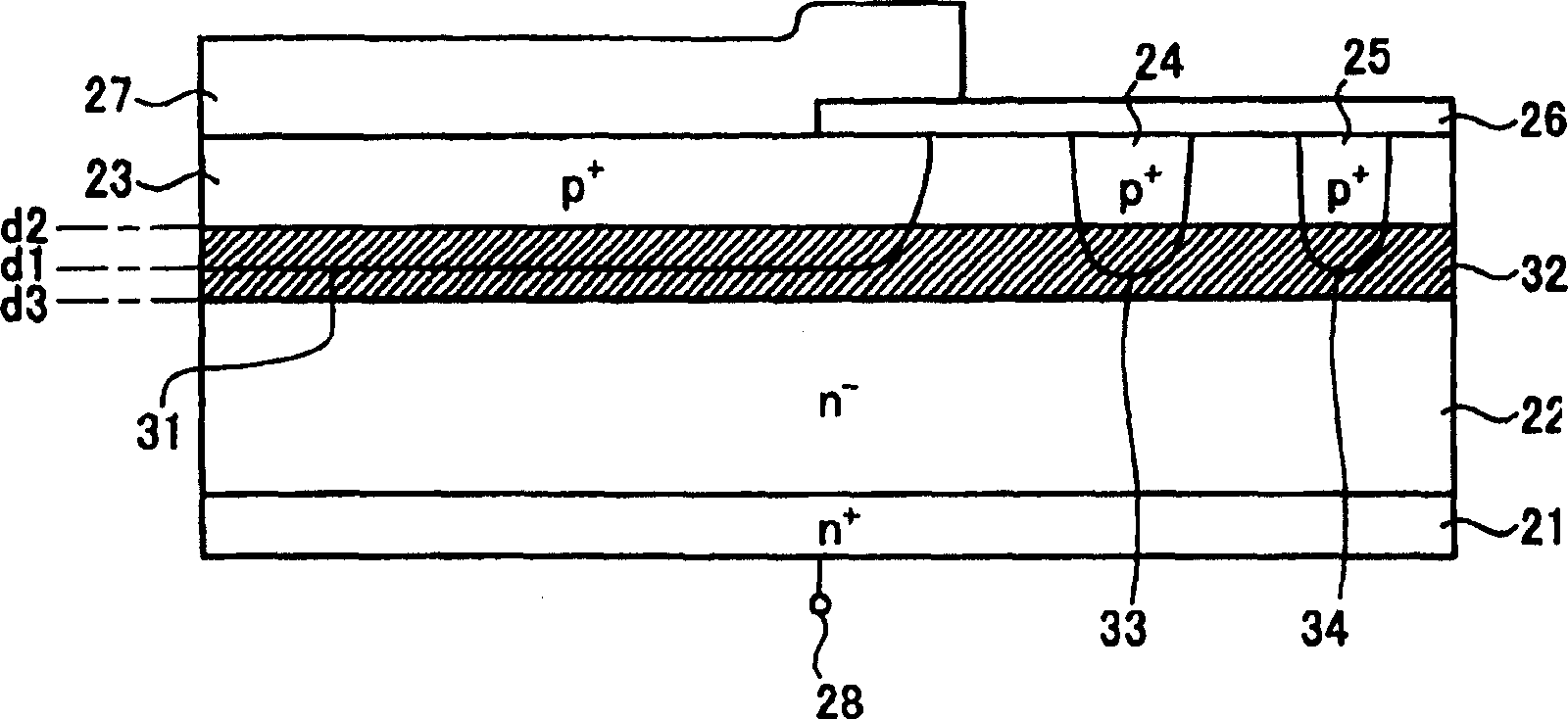
[0040] figure 1 is a cross-sectional view showing a planar PIN diode structure according to one embodiment of the present invention. like figure 1 As shown in n + On the semiconductor layer 21, the n that is the cathode region is set - semiconductor layer 22 . As the diode is in the active region allowing current to flow, the n - On the surface layer of the semiconductor layer 22, an anode region p + Diffusion zone 23.

[0041] Also, in the voltage withstand structure portion on the outside of the active region, in n - On the surface layer of the semiconductor layer 22, p + Diffusion zones 24 and 25. The surface of the voltage-resistant structure is covered with SiO 2 The insulating film 26 of the film. p + The diffusion layer 23 is in contact with t...


PUM


Abstract

A semiconductor device has an n--semiconductor layer and p+-diffusion regions each having a depth of 14 to 20 mum (design value) selectively formed in the n- semiconductor layer. With the entire surface of the chip irradiated with light ions, such as He ions, a lifetime killer is introduced from a position d 2 shallower than a position d 1 of a p-n junction surface, formed from the n--semiconductor layer and the p+-diffusion regions, to a position d 3 deeper than the position d 1 to form a short-lifetime region over the entire chip. The irradiation is carried out so that the light ion irradiation half width is not more than the depth of the p+-diffusion regions and a position of a peak of the light ions becomes deeper than the light ion irradiation half width and within the range between 80% and 120% of the depth of the p+-diffusion regions. Thus, in a semiconductor device such as a converter diode, a capability for a high decay rate of a reverse recovery current di / dt can be brought sufficiently high to such an extent that the device can withstand a lightening surge with a low forward voltage VF being kept low.

Description

technical field [0001] The present invention relates to a semiconductor device mounted on a module such as a power supply module and a manufacturing method thereof, and more particularly to a semiconductor device and a manufacturing method thereof which are highly resistant to lightning strikes applied to the semiconductor module. Background technique [0002] Image 6 is a circuit diagram showing an example of an automotive power supply module. like Image 6 As shown in , the power module is configured with a converter section 1 , an interrupt section 2 , an inverter section 3 and a thermistor 4 . The converter part 1 has converter diodes 5, which generally each consist of a PIN diode. For example, for a module with a rated voltage of 1200V or 600V, a PIN diode with a breakdown voltage of 1600V or higher or 800V or higher, respectively, would be used as a converter diode 5 . [0003] The reason why a breakdown voltage greater than the rated voltage is required is that som...

Claims


Application Information

Patent Timeline
Patent Type & Authority Applications(China)
IPC IPC(8): H01L29/861H01L21/00H01L21/265H01L29/32H01L29/78H01L31/00H01L31/0264H01L31/105H01L31/18
CPCH01L31/0264H01L31/105Y02E10/50H01L31/186H01L29/0619H01L29/32H01L29/868Y02P70/50
Inventor 松井俊之星保幸小林靖幸宫坂靖
Owner FUJI ELECTRIC CO LTD
Learn More