Light engine with LED switching array

a technology of led switching array and light engine, which is applied in the direction of basic electric elements, electric lighting sources, electric light sources, etc., can solve the problems of complex circuits, bulky circuits, and ac-dc drivers such as the on

Active Publication Date: 2013-02-21
HUIZHOU LIGHT ENGINE LTD
View PDF21 Cites 55 Cited by
  • Summary
  • Abstract
  • Description
  • Claims
  • Application Information

AI Technical Summary

Benefits of technology

[0008]In accordance with an aspect of the present invention, an LED array switching apparatus comprises, on a single PCB substrate: a plurality of LED arrays D1 to Dn connected in series, each LED array having a forward voltage; an AC voltage supply coupled to the plurality of LED arrays; and a plurality of constant current sources G1 to Gn, coupled to outputs of LED arrays D1 to Dn, respectively, each of the constant current sources being switchable between a current regulating state and an open state such that as the voltage of the AC voltage supply increases, LED arrays are switched on and lit to form a higher forward voltage LED string, and as the voltage of the AC voltage supply decreases, LED arrays are switched off and removed from the LED string starting with the most recently lit LED array.

Problems solved by technology

AC-DC drivers such as the one shown in FIG. 1 are complex and bulky circuits.

Method used


Image

  • Light engine with LED switching array
  • Light engine with LED switching array
  • Light engine with LED switching array

Examples


Embodiment Construction

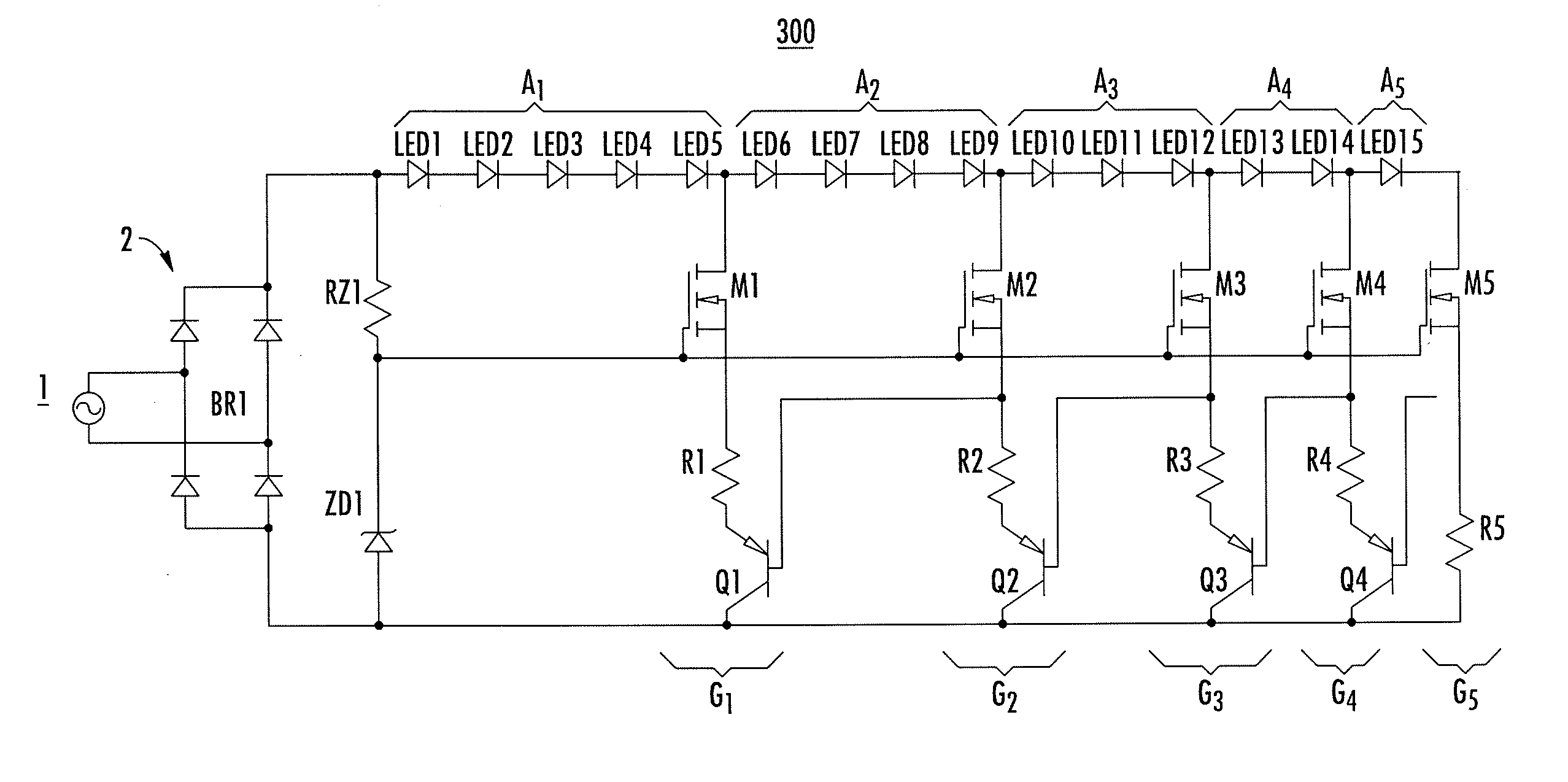
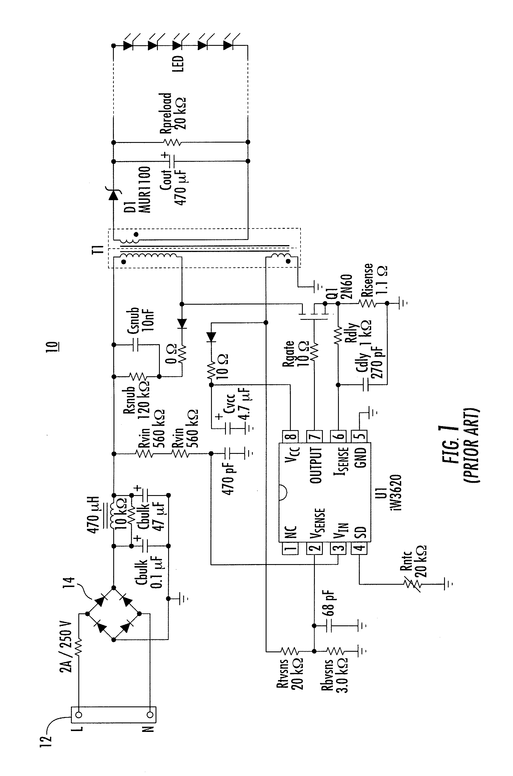
[0030]In order to retain the simple AC connection of an AC LED circuit design, while reducing light off-time associated with conventional AC LED circuits, in accordance with aspects of the present invention, an AC light engine is built on a single PCB with multiple LED arrays and switchable current sources. In contrast to conventional AC-DC LED drivers, such as the one shown in FIG. 1, which are complex and bulky, a driving circuit in accordance with the present invention is simple and small in size, allowing it be packed together with LEDs on a single PCB to form a light engine. The switching configuration in accordance with the present invention can be powered by AC mains directly, and is simple and small enough to pack with the LEDs to form a LED light engine / module which can be powered directly from the AC line. In accordance with the present invention, the driving circuit and the LEDs can be put together on a single PCB.

[0031]FIG. 4 shows the functional blocks of proposed LED d...


PUM


Abstract

An LED array switching apparatus comprises, on a single PCB substrate: a plurality of LED arrays D1 to Dn connected in series, each LED array having a forward voltage; an AC voltage supply coupled to the plurality of LED arrays; and a plurality of constant current sources G1 to Gn, coupled to outputs of LED arrays D1 to Dn, respectively, each of the constant current sources being switchable between a current regulating state and an open state such that as the voltage of the AC voltage supply increases, LED arrays are switched on and lit to form a higher forward voltage LED string, and as the voltage of the AC voltage supply decreases, LED arrays are switched off and removed from the LED string starting with the most recently lit LED array.

Description

CROSS-REFERENCE TO RELATED APPLICATIONS[0001]This utility application claims the benefit under 35 U.S.C. §119(e) of U.S. Provisional Patent Application No. 61 / 524,163, filed Aug. 16, 2011, the entirety of which is incorporated herein by reference.BACKGROUND OF THE INVENTION[0002]The present invention generally relates to improved methods and apparatuses for driving light emitting diodes (“LEDs”), such as those used in LED lamps and lighting fixtures, and improved methods and apparatus for driving that facilitate locating driving circuitry and the LEDs together on a single package.[0003]Typically, the use of LEDs as an AC powered light source requires a driver to convert AC line power to a regulated DC power for maintaining constant light output. Such an LED driver is a self-contained power supply that has output matched to the electrical characteristics, such as forward voltage and driving current, of the LED. Usually, the driver is built on an individual PCB and connects to an LED ...

Claims


Application Information

Patent Timeline
Patent Type & Authority Applications(United States)
IPC IPC(8): H05B37/00H05B44/00
CPCH01L2224/48137H01L2224/48472H01L2224/73265H01L2924/13091H05B33/0824H01L2924/30107H05B33/0803H01L2924/00H05B45/44H05B45/30
Inventor SIU, KAM WAHLEUNG, WA HING
Owner HUIZHOU LIGHT ENGINE LTD
Why Eureka
Try Eureka