Blood pump with separate mixed-flow and axial-flow impeller stages and multi-stage stators

a blood pump and impeller technology, applied in the field of pumps, can solve problems such as red blood cell damage in blood pumps, and achieve the effects of reducing the risk of damage to red blood cells over time, and reducing the circumferential component of the flow

Inactive Publication Date: 2014-11-20
HEARTWARE INC
View PDF62 Cites 34 Cited by
  • Summary
  • Abstract
  • Description
  • Claims
  • Application Information

AI Technical Summary

Benefits of technology

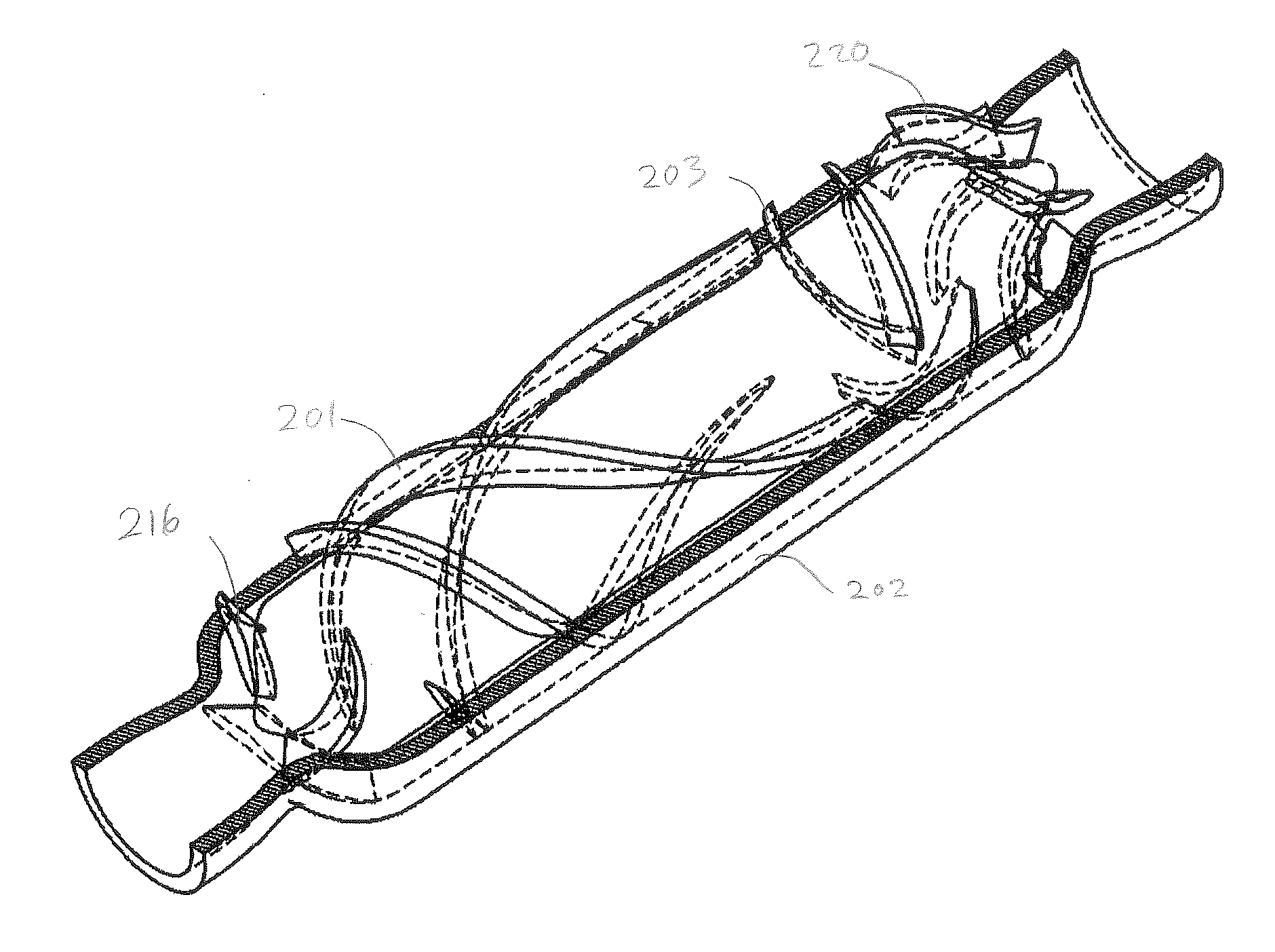
[0011]Exemplary embodiments may provide an apparatus and method for a multistage fluid pump for pumping a fluid such as blood or other fluid, in which a pump has a rotor hub having leading and trailing portions adjacent an inlet and an outlet of the pump, respectively, and an intermediate portion between the leading and trailing portions. A rotor stage comprising at least one impeller blade is positioned at the leading portion of the pump. A stator stage comprising at least one stator blade extends radially inward from a stator housing in a portion of a fluid pathway that surrounds the intermediate portion and is configured to reduce a circumferential component of a flow. As used herein, “radial” or “radially” mean in a radial direction away from a rotational axis of the pump. An axial dimension of the at least one stator blade is smaller than a diameter of the intermediate portion of the rotor hub. As used herein, “axial” dimension means a dimension along or parallel to the pump's rotational axis. A reduced axial dimension of the stator blade reduces contact between the stator blade and components of a fluid, such as red blood cells, for example, and may help reduce risk of damage to red blood cells over time. A second stator stage comprising at least one second stage stator blade may be positioned in a trailing pathway portion of the fluid pathway that surrounds the trailing portion of the rotor, and may reduce a circumferential component of a flow. In a particular example, a transitional outflow region of the stator housing encompassing the trailing pathway portion may define an interior conical space and the at least one second stage stator blade can extend inwardly into the conical space.
[0012]High efficiency, low blood damage, and small compact size are often desirable features for a long-term implantable blood pump. A reduction in the size of the pump may be facilitated by a stator blade positioned within an intermediate fluid pathway portion for reducing a circumferential component of the flow, thereby improving a rotational stability of the pump, and possibly allowing the pump to operate with smaller, more lightweight, or less complicated bearings. A reduction in risk of blood cell damage may be facilitated by a stator blade configuration in which each stator blade has a smaller axial dimension than heretofore contemplated, such as an axial dimension that is less than a diameter of an intermediate portion of the rotor hub. Red blood cell damage in blood pumps is mainly related to the shear stress and degree to which the red blood cells contact other surfaces such as impeller blades and stator blades when passing through the flow paths.
[0013]Efficiency may also be improved when fluid is directed through a first stage rotating mixed-flow type impeller to gain both kinetic energy and pressure rise and then further to gain kinetic energy and pressure rise from passage through second rotating axial impeller region after passage through the stator blade region. Such operation may yield a total higher head (i.e., pressure rise) at the same pump speed than a single stage mixed-flow or single axial flow configuration thus resulting in increased pump efficiency. Alternatively, it may be possible to operate the multiple impeller stage pump at a lower speed and produce the same pressure rise as a single impeller stage configuration. The higher efficiency provides the benefit of low temperature rise of the motor and longer battery life. As contact with bodily tissues is inherent to the device, the reduction in operating temperatures can reduce risks associated with contact to surrounding body tissues. In addition, higher shear stress regions in blood pumps usually occur in the blade tip gap regions, which are directly related to the pump speed. A two-stage impeller design requires a lower pump speed than a purely single stage mixed-flow or axial flow blood pump in order to generate about 150 mmHg pressure rise for the need of a human body.

Problems solved by technology

Red blood cell damage in blood pumps is mainly related to the shear stress and degree to which the red blood cells contact other surfaces such as impeller blades and stator blades when passing through the flow paths.

Method used


Image

  • Blood pump with separate mixed-flow and axial-flow impeller stages and multi-stage stators
  • Blood pump with separate mixed-flow and axial-flow impeller stages and multi-stage stators
  • Blood pump with separate mixed-flow and axial-flow impeller stages and multi-stage stators

Examples


Embodiment Construction

[0025]For purpose of illustration, discussions of the technology will be made in reference to its utility as a cardiac assist blood pump. However, it is to be understood that the technology may have a variety of wide applications to many types of turbomachinery including, for example, commercial and industrial pumps, compressors, and turbines.

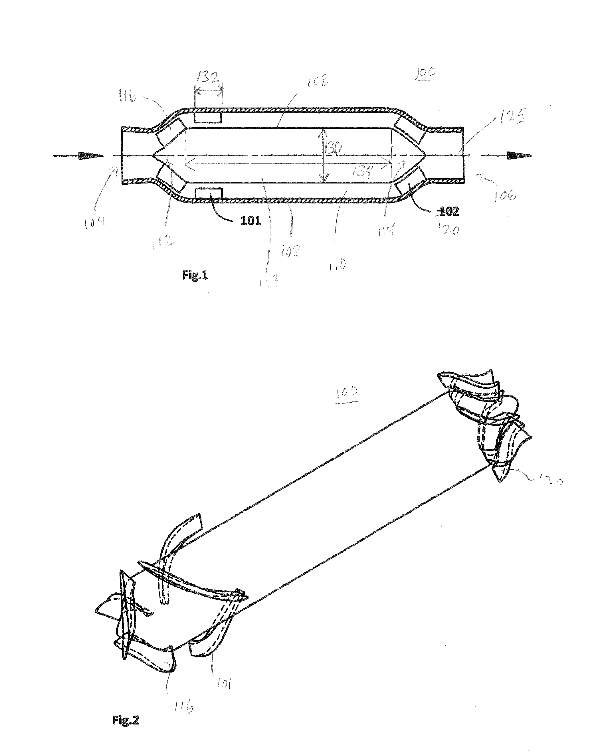
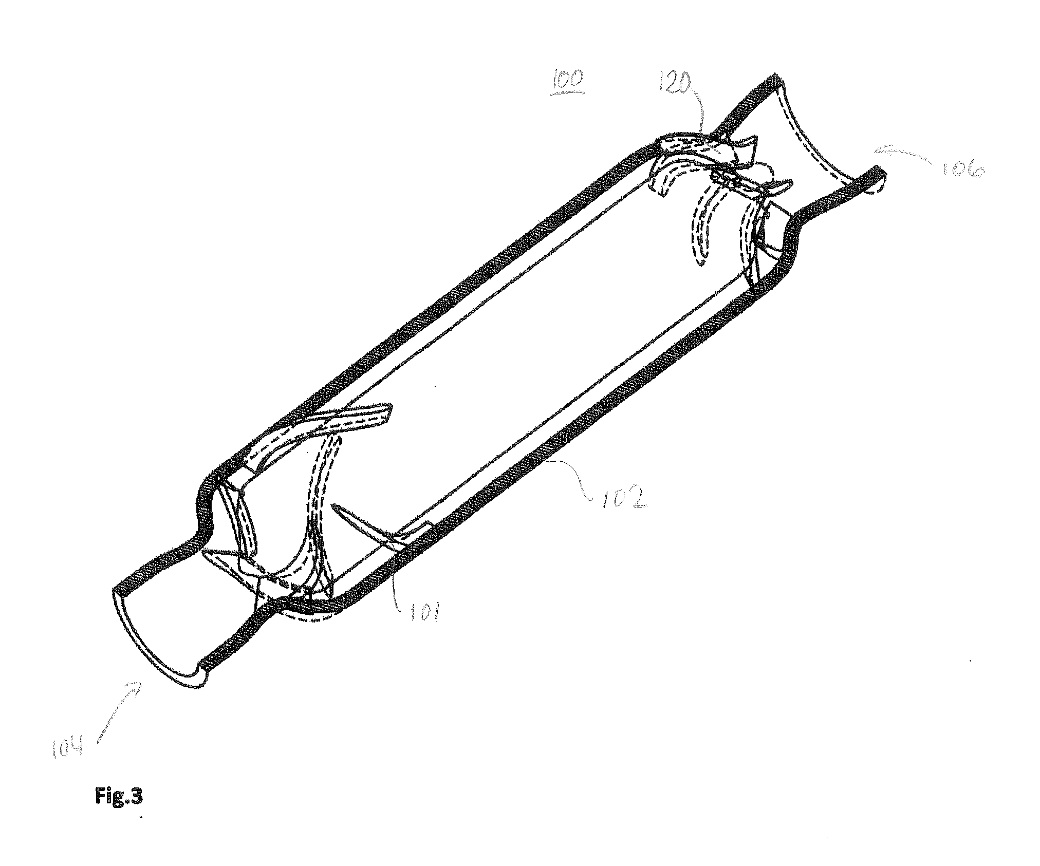
[0026]Referring to FIGS. 1 through 3, a rotordynamic blood pump 100 is shown in accordance with an embodiment of the present invention. FIG. 1 shows a meridional section of the pump 100. FIG. 2 shows a perspective view of various components of the pump, the housing of the pump being removed from the view for purposes of clarity. FIG. 3 shows a perspective view of the pump 100 with the housing being sectioned to provide context to other components of the pump 100. Aspects of rotordynamic blood pumps are disclosed in co-pending U.S. patent application Ser. No. 13 / 275,912 filed Oct. 18, 2011, and 13 / 276,009 filed Oct. 18, 2011, the disclosures of ...


PUM


Abstract

A pump for a fluid which can be blood has a stator housing and a rotor hub with leading and trailing portions and an intermediate portion disposed therebetween. At least one impeller blade at the leading portion drives circumferential and axial components of a flow into a pump annulus or intermediate pathway portion. At least one stator blade extends radially inward from the stator housing within the intermediate pathway portion and is configured to reduce a circumferential component of the flow.

Description

CROSS-REFERENCE TO RELATED APPLICATIONS[0001]This application claims the benefit of the filing date of U.S. Provisional Patent Application No. 61 / 823,224 filed May 14, 2013, the disclosure of which is incorporated by reference herein.BACKGROUND OF THE INVENTION[0002]1. Technical Field[0003]This invention relates generally to pumps. More specifically, this invention relates to blood pumps, such as cardiac assist pumps that may be implanted in a patient.[0004]2. Description of the Related Art[0005]Rotordynamic pumps, such as centrifugal, mixed-flow, and axial-flow pumps with mechanical bearings or magnetically suspended systems, have been widely used as a ventricular assist devices to support patients with heart diseases. In magnetically levitated blood pumps, which generally include an impeller that is both magnetically suspended and rotated without mechanical means, an annular gap located between the rotor and stator suspension and drive components is conventionally designed to be r...

Claims


Application Information

Patent Timeline
Patent Type & Authority Applications(United States)
IPC IPC(8): A61M1/10F04D3/02A61M60/178A61M60/221A61M60/232A61M60/237A61M60/408A61M60/806A61M60/81A61M60/82
CPCF04D3/02A61M1/101F04D1/025F04D1/04F04D3/00A61M60/148A61M60/82A61M60/408A61M60/81A61M60/232A61M60/237A61M60/178A61M60/806A61M60/221
Inventor WU, JINGCHUNRICCI, MICHAELPADEN, DAVIDSNYDER, SHAUN
Owner HEARTWARE INC
Why Eureka
Try Eureka