Yoga mat with support and traction
a technology of yoga mats and supports, applied in the field of yoga mats and yoga towels, can solve the problems of reducing the performance of users, increasing the likelihood of injuries, and inability to provide sufficient traction in certain areas of yoga mats, so as to achieve lower compressibility, lower compressibility, and higher compressibility
- Summary
- Abstract
- Description
- Claims
- Application Information
AI Technical Summary
Benefits of technology
Problems solved by technology
Method used
Image
Examples
first embodiment
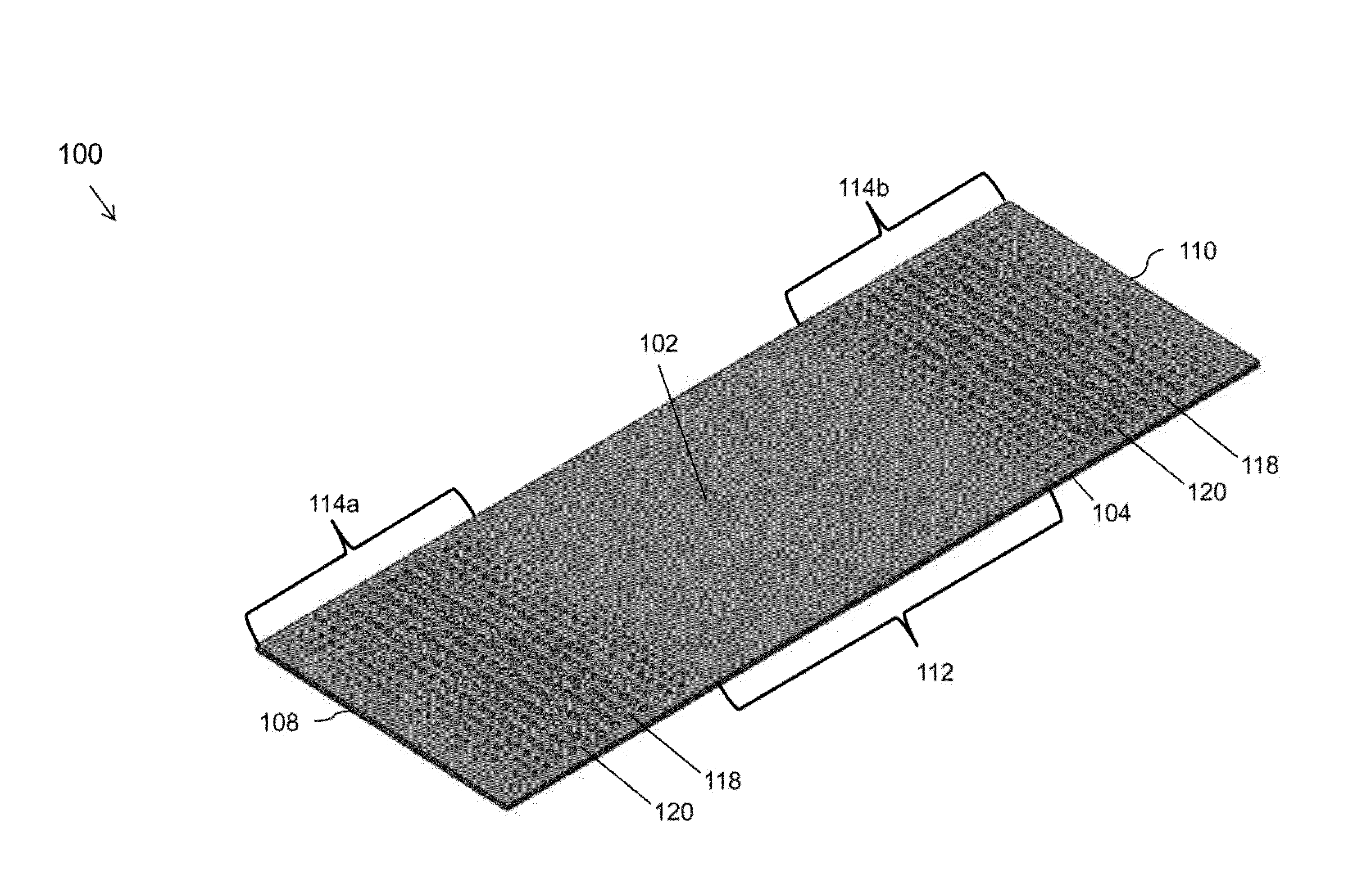
[0094]FIGS. 4A and 4B depict compressed and uncompressed configurations of a mat 400, in accordance with the present disclosure. As shown in FIGS. 4A and 4B, the mat 400 includes a first layer 402 having a top surface 408 and a bottom layer 404 disposed below the first layer 402. The top surface 408 of the first layer 402 in the grip zone may include one or more first portions 410. The top surface 408 of the first layer 402 in the grip zone other than the first portions 410 forms one or more second portions 412. As shown in FIGS. 4A and 4B, the second portions 420 are the portions on the top surface 408 of the first layer 402 in the grip zone that are disposed between the first portions 410.
[0095]As depicted in FIGS. 4A and 4B, a plurality of columns 414 formed of an elastomer may be introduced into openings 418 formed through the first portions 410. The columns 414 may have the top surfaces 420 that are coplanar to the top surface 408 of the first layer 402. Further, as shown in FI...
second embodiment
[0099]FIGS. 5A and 5B depict compressed and uncompressed configurations of a mat 500, in accordance with the present disclosure. Various elements or configurations in this embodiment are the same as that disclosed in conjunction with FIGS. 4A and 4B, except that columns 502 are constructed differently. The individual columns 502 are formed by pouring the liquid elastomer into the openings 418 and curing the elastomer. As a result, the sides of the columns 502 are bonded to the sides of the openings 418. Further, as illustrated in FIG. 5B, the sides of the openings 418 are only partially compressed and thus, only a small portion of the columns 502 is exposed to the top surface 408 of the first layer 402 when subjected to pressure equal to or greater than the threshold pressure. However, portions of the individual second portions 412 of the top surface 408 of the first layer 402 surrounding the columns 502 compress such that the columns 502 protrude further than the surrounding portio...
third embodiment
[0100]FIGS. 6A and 6B depict compressed and uncompressed configurations of a mat 600, in accordance with the present disclosure. Various elements or configurations in this embodiment are the same as that disclosed in conjunction with FIGS. 4A and 4B, except that columns 602 are formed of a material that is more compressible than the material used to form the second portions 412 of the top surface 408 of the first layer 402. As a result, as illustrated in FIG. 6B, top surfaces of the columns 502 depress or compress more than the second portions 412 in response to the pressure applied on the grip zone. In one embodiment, the threshold pressure at which the columns 502 may begin to compress may be different from the threshold pressure at which the second portions 412 may begin to compress. Alternatively, in another embodiment, the threshold pressures for both the columns 502 and the second portions 412 may be the same; however, the columns 502 may compress more than the second portions...
PUM
 Abstract
Description
Claims
Application Information
 - R&D
- Intellectual Property
- Life Sciences
- Materials
- Tech Scout
- Unparalleled Data Quality
- Higher Quality Content
- 60% Fewer Hallucinations
Browse by: Latest US Patents, China's latest patents, Technical Efficacy Thesaurus, Application Domain, Technology Topic, Popular Technical Reports.
© 2025 PatSnap. All rights reserved.Legal|Privacy policy|Modern Slavery Act Transparency Statement|Sitemap|About US| Contact US: help@patsnap.com


